Packing wear condition monitoring device

A wear state and monitoring device technology, which is applied in the direction of testing wear resistance, wellbore/well components, earthwork drilling and production, etc., can solve problems such as increasing motor power, shortening service life of packing, polluting wellhead and atmospheric environment, etc., to achieve Increase the service life, reduce friction loss, and improve the effect of lubrication environment

Pending Publication Date: 2018-09-04
辽宁众森装备制造有限公司
View PDF0 Cites 8 Cited by
  • Summary
  • Abstract
  • Description
  • Claims
  • Application Information

AI Technical Summary

Problems solved by technology

[0002] The distribution of oil pumping units in oil production is scattered and covers a wide area. There is no accurate dynamic data on the sealing status of polished rods in each well. Leakage state, after the maintenance of the polished rod packing box once, it is impossible to control when the next maintenance will be performed. It can only be monitored by increasing the frequency of well patrolling, and the workload and work intensity are relatively large.
[0003] In order to prevent running, blowout and blowout, fastening or replacing the polished rod sealing packing has become a key task. At the same time, the underground mining process is becoming more and more complex, and the formation pressure is erratic. The polished rod packing box currently used cannot follow the sudden pressure rise in the well When the sealing force is increased, it often happens that after checking during the day, running, blowout and blowout occur at night, which pollutes the environment and causes production accidents, which also puts a lot of psychological and management pressure on the oil production workers.
[0004] During the oil extraction process, the polished rod will vibrate, twist, and positionally deviate from the donkey head of the pumping machine, which will cause the packing to be used in poor conditions. The packing cannot adapt to the dynamics of the polished rod when it is sealed, and the service life of the packing will be shortened and replaced frequently.
[0005] At present, in the existing polished rod sealer, the packing work depends on the axial compression force generated by the pressure cap on the packing box. When moving downward, the friction force between the packing and the polished rod and the axial compression force of the packing are superimposed, the pressure on the lower part of the packing increases, and the friction between the lower part of the packing and the polished rod also increases. At this time, the sealing state of the packing box is tight at the bottom and loose at the top. , in the same way, when the polished rod moves upwards, the packing of the packing box will be tightened and loosened, and the cycle will be repeated, and the fluid in the well will overflow from the polished rod. The traditional packing box compresses and seals the packing to make the packing The control of strength has become a headache for the on-site workers. If the compression force of the packing is too large, the friction force of the packing at the upper and lower ends of the packing box will be greater, resulting in poor lubrication of the polished rod and serious wear of the packing. Shortened service life also damages the polished rod. At the same time, the friction resistance is too large, which increases the power of the motor and causes waste; too small fastening force of the packing will cause leakage of the packing and pollute the wellhead and the atmospheric environment; It is determined by the tightening strength of the on-site workers. If the leak is still leaked after being tightened with the maximum tightening force, the packing must be replaced. Relying on experience to determine the replacement of the packing brings convenience to the on-site work, but However, the utilization efficiency of the packing is low, the life is short, the labor intensity of the workers is increased, and the production cost is increased.

Method used


Image

  • Packing wear condition monitoring device
  • Packing wear condition monitoring device

Examples


Embodiment Construction

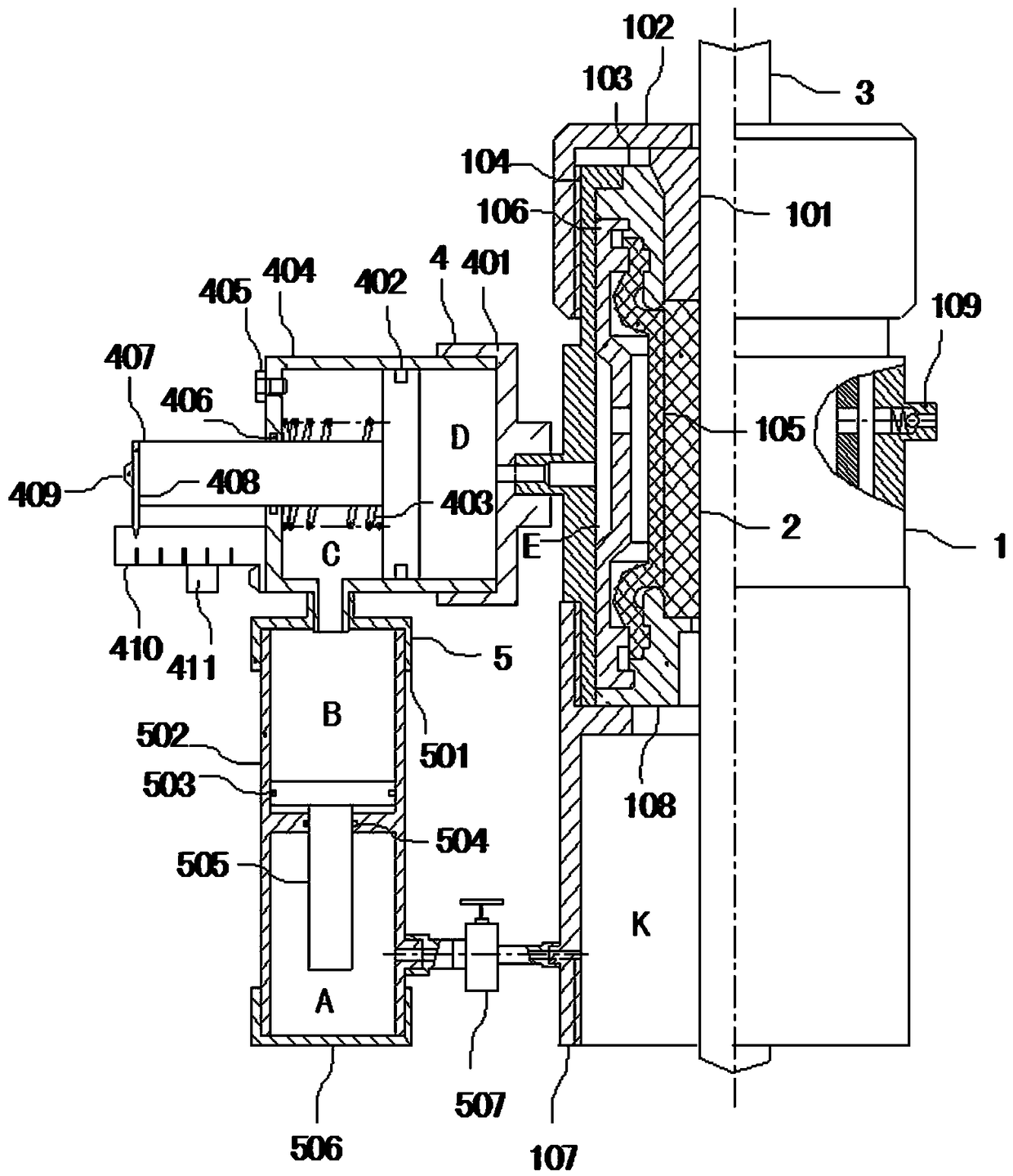
[0022] Such as figure 1 As shown, the packing wear state monitoring device includes a packing bin 1, a metering mechanism 4 and a pressure matching cylinder 5; the bottom of the stuffing bin 1 is fixedly connected to the wellhead components; the stuffing bin 1 includes a casing 104, a shield 106, The rubber tube 105 and the packing 2; the rubber tube 105 and the packing 2 are respectively placed in the housing 104; the cursor 3 is located on the central axis of the housing 104; the packing 2 and the rubber tube 105 are sequentially socketed with the cursor 3 The end of the shield 106 is fixedly connected to the end of the rubber cartridge 105; the inner wall of the housing 104 and the outer wall of the rubber cartridge 105 form a pressure chamber E; an oil filling valve 109 is fixedly provided on the outer housing 104; The oil injection valve 109 communicates with the pressure chamber E.

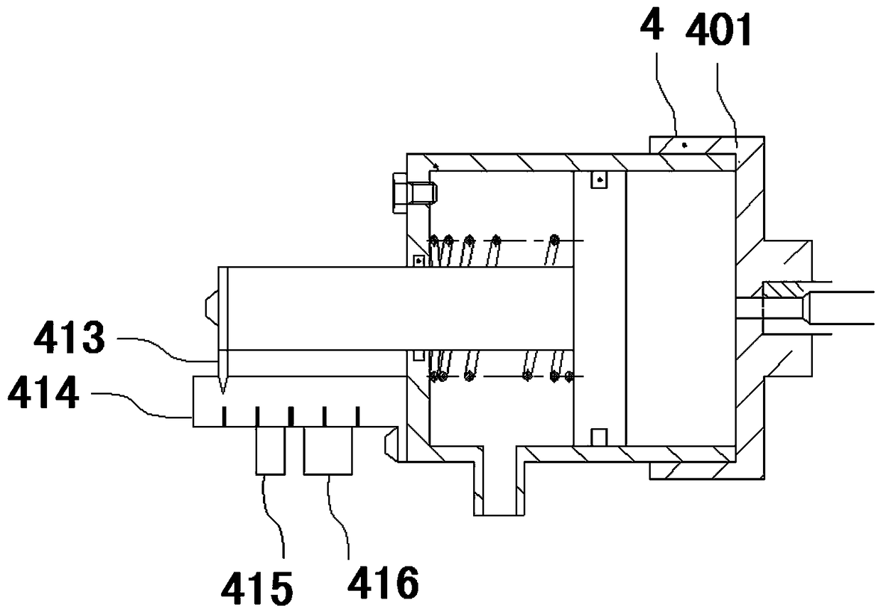
[0023]The metering mechanism 4 includes a cylinder 404, a piston 407 and a piston rod 4...


PUM


Abstract

The invention belongs to the technical field of oil production well tools, in particular to a packing wear condition monitoring device, which comprises a filling chamber (1), a metering mechanism (4)and a pressure matching cylinder (5), wherein the filling chamber (1) comprises a shell (104), a shield (106), a rubber cylinder (105) and a packing (2); the rubber cylinder (105) and the packing (2)are separately placed in the shell (104); a cursor (3) is located at a middle shaft of the shell (104); the packing (2) and the rubber cylinder (105) are sequentially sleeved with the cursor (3); theend of the shield (106) is fixedly connected with the end of the rubber cylinder (105); a pressure chamber E is defined by the inner wall of the shell (104) and the outer wall of the rubber cylinder (105). The packing wear condition monitoring device can be used to prolong the service life of the packing, provide on-site information and remote information of the working wear condition of the packing, perform real-time control on the sudden increase of pressure underground, reduce the working intensity of oil producing workers and lower the production risk.

Description

technical field [0001] The invention belongs to the technical field of well tools for oil exploitation, and in particular relates to a packing wear state monitoring device. Background technique [0002] The distribution of oil pumping units in oil production is scattered and covers a wide area. There is no accurate dynamic data on the sealing status of polished rods in each well. In the state of leakage, after one maintenance of the polished rod packing box, it is impossible to control when the next maintenance will be performed. It can only be monitored by increasing the frequency of well patrols, and the workload and intensity are relatively large. [0003] In order to prevent running, blowout and blowout, fastening or replacing the polished rod sealing packing has become a key task. At the same time, the underground mining process is becoming more and more complex, and the formation pressure is erratic. The polished rod packing box currently used cannot follow the sudden ...

Claims


Application Information

Patent Timeline
Patent Type & Authority Applications(China)
IPC IPC(8): G01N3/56E21B23/00
CPCG01N3/56E21B23/00
Inventor 赵立凯
Owner 辽宁众森装备制造有限公司
Why Eureka
Try Eureka