
Bionic air chamber used for hand-held electronic nose

A technology of imitation air chamber and electronic nose, which is applied in the field of imitation air chamber, can solve the problems of air flow blockage, long sampling time, too large air chamber, etc., and achieve the effects of easy cleaning, shortening sampling time and ensuring fluidity

Inactive Publication Date: 2018-09-04
TIANJIN UNIV
View PDF13 Cites 4 Cited by
  • Summary
  • Abstract
  • Description
  • Claims
  • Application Information

AI Technical Summary

Problems solved by technology

The current electronic nose air chamber has more or less the following problems: (1) The air pressure value at the sensor array area is too small, and the gas cannot fully contact with the sensor; (2) The air flow is blocked inside the air chamber, which is not conducive to the electronic nose. (3) The air chamber is too large, which is not conducive to the design of the hand-held electronic nose
This air chamber structure does not take into account the influence of the internal structure of the air chamber on the sensor, and the air chamber structure is too large, which is not conducive to the design of the handheld electronic nose

Method used


Image

  • Bionic air chamber used for hand-held electronic nose
  • Bionic air chamber used for hand-held electronic nose
  • Bionic air chamber used for hand-held electronic nose

Examples


Embodiment Construction

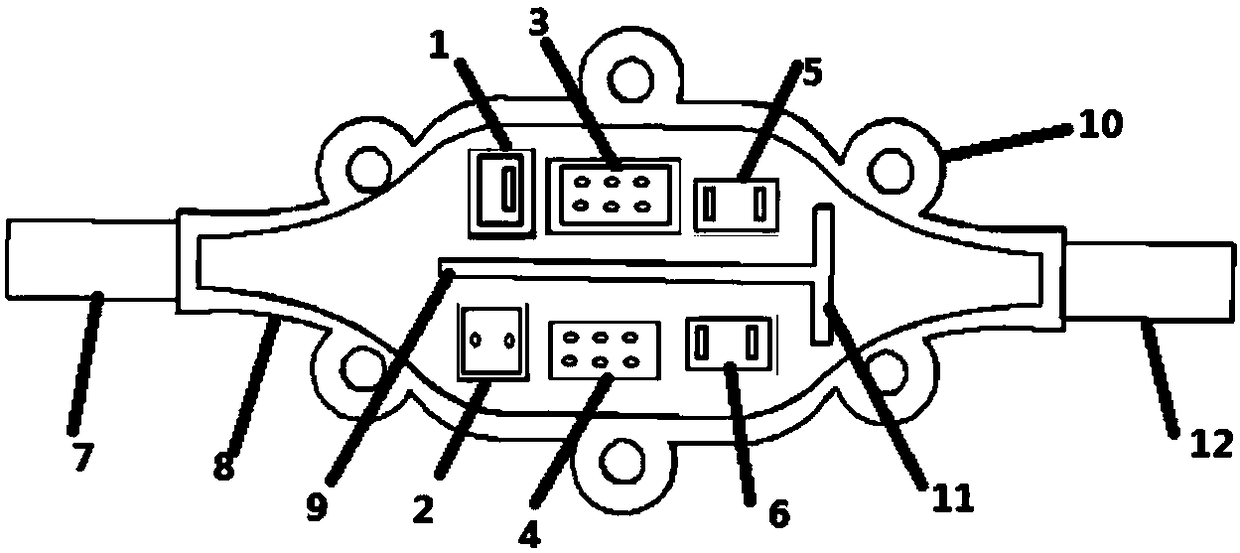
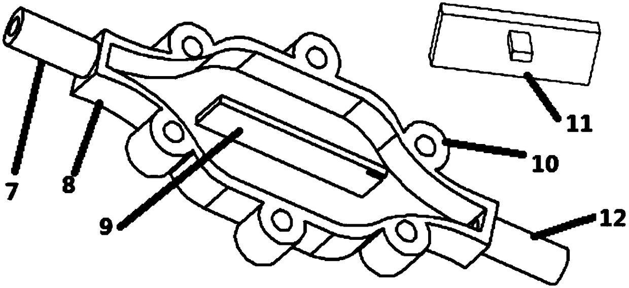
[0025] Since the sensor array of the existing electronic nose system is generally used as a single hardware module, the air chamber needs to place the entire sensor array module in its cavity, and the volume of the air chamber is relatively large. In the novel air chamber structure of the present invention, the sensor array and other hardware modules are welded on a circuit board, and the design of the air chamber is affected by the size and quantity of the sensors. In this patent, there are 6 patch sensors, the gas chamber and the sensor are closely combined, the volume of the gas chamber is small, and the length, width and height are 52mm, 20mm and 6mm respectively.

[0026] In order to make the air flow more stable and fast, the inlet and outlet of the air chamber adopt a streamlined structure; in order to maintain uniform air pressure before and after the sensor array and reduce the length of the air chamber, the placement of the sensors in the cavity is divided into two ro...


PUM


Abstract

The invention relates to a bionic air chamber used for a hand-held electronic nose. The bionic air chamber used for the hand-held electronic nose comprises an air chamber wall and a bottom, a paster sensor is fixed at the bottom, the bionic air chamber is characterized in that a shape from an inlet to an outlet at the inner surface of the wall of the air chamber is a streamline, the middle size inthe air chamber is greater than the inlet size and the outlet size, and the bionic air chamber has the characteristics of small port and large chamber. The middle separation plates are vertically distributed in the air chamber, a slot used for fixing a baffle plate is arranged at the middle separation plate near the outlet end, a plugboard cooperated with the slot is arranged at the baffle plate,and the air pressure in the air chamber and the air-flow speed at the outlet can be adjusted by adjusting the height of the baffle plate.

Description

technical field [0001] The invention relates to a bionic air chamber for a hand-held electronic nose. Background technique [0002] In recent years, electronic nose technology has developed rapidly, and significant progress has been made in agriculture, forestry, food and beverage, alcohol, and medical treatment; electronic noses have also gradually transformed from precise and expensive scientific instruments to portable or handheld electronic devices. The hand-held electronic nose is easy to carry, can be applied to more occasions, and is also conducive to marketing. [0003] At present, the research on electronic nose technology mainly focuses on sensor preparation, pattern recognition algorithm and application, etc., and rarely involves the research on the structure of electronic nose air chamber. The sensor reading is affected by many aspects, such as air pressure, air velocity, etc., and the air flow characteristics are affected by the structure of the air chamber. T...

Claims


Application Information

Patent Timeline
IPC IPC(8): G01N33/00
CPCG01N33/0001
Inventor 孟庆浩晋兴威亓培锋
Owner TIANJIN UNIV
Learn More