
Virtual synchronous generator-based rotational inertia optimization control method
A technology of virtual synchronization and moment of inertia, applied to electrical components, circuit devices, AC network circuits, etc., can solve problems such as inverter output power and frequency oscillation, transient anti-interference ability and overload ability, shutdown, etc., to achieve Solve the shock and take into account the effect of running stability
- Summary
- Abstract
- Description
- Claims
- Application Information
AI Technical Summary
Problems solved by technology
Method used
Image

Examples
Embodiment Construction
[0043] The principle and specific implementation of the present invention will be described below in conjunction with the accompanying drawings.
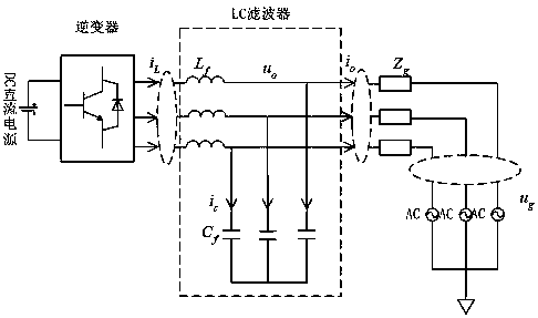
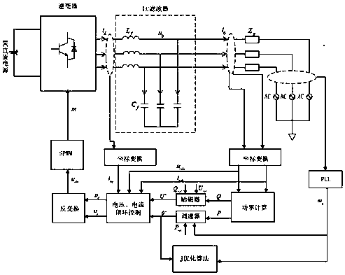
[0044] figure 1 It is the main circuit topology and control structure diagram of the micro-grid inverter of the present invention. By optimizing the control of the moment of inertia, the oscillation of the output power and frequency of the inverter can be avoided, and the stable operation of the protection system can be maximized.
[0045] The steps of the present invention are:
[0046] Step 1, collect the grid voltage e within a switching cycle a 、e b 、e c , the output capacitor voltage u of the microgrid inverter oa , u ob , u oc , bridge arm side inductor current i La i Lb i Lc and the output side current i oa i ob i oc , the capacitance voltage u in the synchronous rotating coordinate system is obtained by coordinate change od , u oq , the inductor current i Ld i Lq and output current i od i oq ;
[0047] Step ...
PUM
 Abstract
Description
Claims
Application Information