Forward-flyback dual-path balanced load switching power supply circuit

A switching power supply circuit, balanced load technology, applied in electrical components, adjusting electrical variables, instruments, etc., can solve the problems of low power density, the same switching frequency, large ripple and noise interference, etc., to achieve low current stress, secondary The effect of halving the wire diameter and increasing the power density

Pending Publication Date: 2018-09-04
SHENZHEN ZHENHUA MICROELECTRONICS
View PDF4 Cites 2 Cited by
  • Summary
  • Abstract
  • Description
  • Claims
  • Application Information

AI Technical Summary

Problems solved by technology

Due to the low efficiency and low power density of the flyback topology, it generates serious heat when it supplies power to high-power positive and negative balanced loads such as power comparators. Ripple and noise need to be filtered by an external filter circuit before use, which increases the complexity of the system
Although the positive dual-circuit balanced load switching power supply has high efficiency and small ripple, its shortcomings such as large size and complex design of output energy storage filter inductors limit its application in positive and negative dual-circuit balanced load power supply systems.
Since the switching frequency of each switching power supply cannot be guaranteed to be exactly the same, simply combining two independent positive and negative switching power supplies to form a positive and negative power supply will introduce huge ripple and noise interference, and difference frequency interference cannot be easily filtered out, so the application effect of this combination method is also relatively limited

Method used


Image

  • Forward-flyback dual-path balanced load switching power supply circuit

Examples


Embodiment Construction

[0018] In order to describe the technical solution of the present invention more clearly and completely, the present invention will be further described below in conjunction with the accompanying drawings.

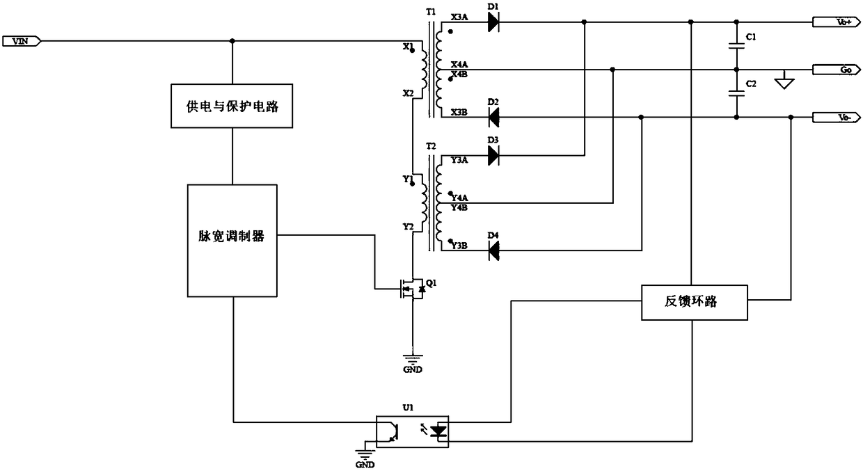
[0019] Please refer to figure 1 , the present invention proposes a forward-flyback dual-circuit balanced load switching power supply circuit, the forward-flyback dual-circuit balanced load switching power supply circuit includes: an input terminal, a first transformer T1, a second transformer T2, and a dual-channel output terminal. The first transformer T1 and the second transformer T2 convert the input direct current at the input terminal into alternating current and output it to the dual output terminals, the primary winding of the first transformer T1 is connected to the input terminal, and the first transformer T1 The primary winding of T1 is connected in series with the primary winding of the second transformer T2, and the secondary winding of the first transformer T1...


PUM


Abstract

The invention discloses a forward-flyback dual-path balanced load switching power supply circuit, which comprises: an input end, a first transformer T1, a second transformer T2 and a dual-path outputend, wherein the first transformer T1 and the second transformer T2 convert a direct current input from the input end into an alternating current and output the alternating current to the dual-path output end, a primary winding of the first transformer T1 is connected with the input end, the primary winding of the first transformer T1 is connected in series with a primary winding of the second transformer T2, and a secondary winding of the first transformer T1 and a secondary winding of the second transformer T2 are connected in parallel and each connected with the dual-path output end. Through designing the forward transformer and the flyback transformer, the forward-flyback dual-path balanced load switching power supply circuit has the advantages of low noise, high efficiency, small ripple, high power density, easy loop design and no right half plane zero point when operating in a continuous mode, since the two transformers transfer energy to the secondary stage simultaneously, the number of turns of the transformers is small, the transformers are easy to wind, the wire diameter of the secondary stage is reduced by half, the current stress on a power switching tube is small and the like.

Description

technical field [0001] The invention relates to the field of switching power supplies, in particular to a forward and flyback dual-circuit balanced load switching power supply circuit. Background technique [0002] Nowadays, positive and negative dual-circuit balanced load switching power supplies are widely used in power supply systems for analog circuits, bipolar positive and negative balanced power supply op amps or comparators, power comparators, and digital-to-analog converters. Because the flyback transformer is easy to design, most switching power supplies with dual balanced loads use the flyback topology. Nowadays, large-scale digital acquisition and digital-to-analog conversion systems or power comparators have higher and higher requirements for power supply capabilities. Due to the low efficiency and low power density of the flyback topology, it generates serious heat when it supplies power to high-power positive and negative balanced loads such as power comparato...

Claims


Application Information

Patent Timeline
Patent Type & Authority Applications(China)
IPC IPC(8): H02M3/335H02M1/14
CPCH02M1/14H02M3/335
Inventor 李炜鹏田仁军
Owner SHENZHEN ZHENHUA MICROELECTRONICS
Why Eureka
Try Eureka