
Horizontal magnetic field type vertical-ring high gradient magnetic separator

A high-gradient magnetic separator and magnetic field technology, applied in high-gradient magnetic separators and other directions, can solve the problems of low background magnetic field strength, inability to classify adsorption, and large separation air gap, so as to improve the separation effect and the utilization of magnetic energy. efficiency, improving the sorting effect and magnetic energy utilization rate, and reducing the effect of magnetic media clogging

Pending Publication Date: 2018-09-07
广东省资源综合利用研究所
View PDF0 Cites 2 Cited by
  • Summary
  • Abstract
  • Description
  • Claims
  • Application Information

AI Technical Summary

Problems solved by technology

In order to increase the processing capacity of the equipment, this type of equipment adopts the method of increasing the width of the swivel, but for the horizontal magnetic field vertical ring high gradient magnetic separator, the width of the swivel is the separation air gap, and increasing the width of the swivel is to increase the separation air gap , the horizontal magnetic field vertical ring high gradient magnetic separator obtained in this way has a large sorting air gap, serious magnetic flux leakage, and large magnetic energy loss, resulting in low background magnetic field strength of the equipment; Significant changes, unable to grade adsorption according to mineral magnetic strength, resulting in low utilization rate of magnetic energy

Method used


Image

  • Horizontal magnetic field type vertical-ring high gradient magnetic separator
  • Horizontal magnetic field type vertical-ring high gradient magnetic separator
  • Horizontal magnetic field type vertical-ring high gradient magnetic separator

Examples


Embodiment 1

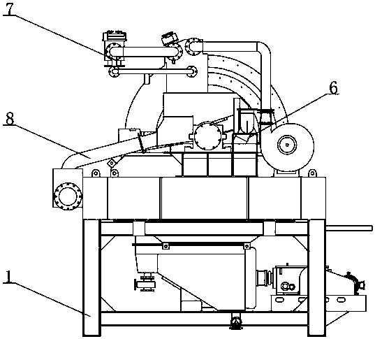
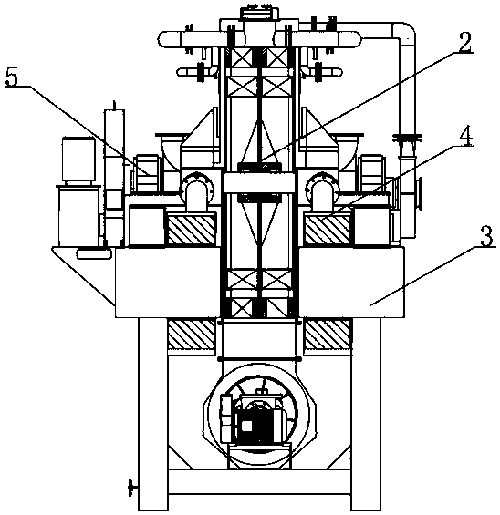
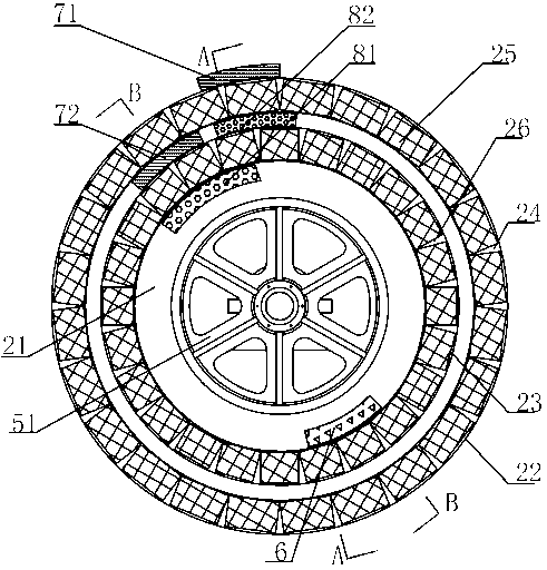
[0033] Such as Figure 1 to Figure 7Shown is the first embodiment of the horizontal magnetic field vertical ring high-gradient magnetic separator of the present invention, including a frame 1, a sorting ring 2 containing magnetic media, a magnetic system 3 fixed on the frame 1, and a magnetic system surrounded by The excitation coil 4 on the 3, the drive mechanism 5 for driving the sorting ring to rotate, the feeding device 6 arranged above the sorting ring 2, the washing device 7 for washing the coarse and fine magnetic materials and the coarse and fine magnetic materials for receiving the sorting The material receiving device 8 for granular magnetic materials, the drive mechanism 5, the feeding device 6, the washing device 7 and the material receiving device 8 are all arranged on the frame 1; A sorting space is formed, and the sorting ring 2 is arranged in the sorting space; the excitation coil 4 cooperates with the magnetic system 3 to form a background magnetic field in wh...

Embodiment 2

[0041] Such as Figure 8 Shown is the second embodiment of the horizontal magnetic field vertical ring high gradient magnetic separator of the present invention, this embodiment is similar to the first embodiment, the difference is that the thickness of the intermediate ring 21 increases radially from outside to inside in two stages , the middle ring 21 includes a first ring and a second ring, the first ring is connected to the outside of the second ring, the thickness of the second ring is greater than the thickness of the first ring; the outer ring includes a first outer ring 22 and a second outer ring 23 , the first ring is embedded inside the first outer ring 22 , and the second ring is embedded inside the second outer ring 23 . The first magnetic field sorting area is formed between the first ring and the first outer ring 22, the second magnetic field sorting area is formed between the second ring and the second outer ring 23, and the magnetic field strength of the first ...

Embodiment 3

[0043] Such as Figure 7 Shown is the third embodiment of the horizontal magnetic field vertical ring high-gradient magnetic separator of the present invention. This embodiment is similar to Embodiment 1, the difference is that in order to increase the stability of the distribution of the induced magnetic field intensity in the sorting space, in the The two sides of an outer ring 21 and a second outer ring 22 are respectively surrounded by a first thickened layer and a second thickened layer made of magnetic permeable material. The best uniform effect is obtained when the total thickness of the first thickened layer and the total thickness of the second thickened layer are respectively equal to the thickness of the first ring and the second ring.


PUM


Abstract

The invention relates to the technical field of magnetic separation equipment, in particular to a horizontal magnetic field type vertical-ring high gradient magnetic separator. The horizontal magneticfield type vertical-ring high gradient magnetic separator comprises a rack, a separation ring, a magnetic system, an exciting coil surrounding the magnetic system, a drive mechanism used for drivingthe separation ring to rotate, a feeding device, a flushing device and a receiving device, wherein separation space is formed in the magnetic system, and the separation ring is arranged in the separation space; a background magnetic field with magnetic field intensity uniformly distributed in the direction of separation height is formed in the separation space by cooperation of the exciting coil and the magnetic system, the separation ring rotates to pass the separation space to change magnetic field distribution of the separation space, and an induced magnetic field in horizontal magnetic field direction and with the magnetic field intensity changing in the direction of separation height is formed in the separation space. By designing the separation ring structure under the condition thatpower consumption is not added, high-low collocation of the magnetic field intensity in the direction of separation height is formed, the separation effect is improved, the magnetic energy use ratiois increased, magnetic medium blockage caused by magnetization agglomeration of magnetic minerals is reduced, and follow-up back flush unloading work is facilitated.

Description

technical field [0001] The present invention relates to the technical field of magnetic separation equipment, more specifically, to a horizontal magnetic field vertical ring high gradient magnetic separator. Background technique [0002] The development of high gradient magnetic separator has gone through three stages: periodic high gradient magnetic separator - continuous flat ring high gradient magnetic separator - continuous vertical ring high gradient magnetic separator, among which continuous vertical ring high gradient magnetic separator Due to the outstanding advantages of continuous operation, large equipment processing capacity, and not easy to block the medium, it is widely used in major mines at home and abroad. Continuous vertical ring high gradient magnetic separator can be divided into vertical magnetic field vertical ring high gradient magnetic separator and horizontal magnetic field vertical ring high gradient magnetic separator according to the direction of ...

Claims


Application Information

Patent Timeline
IPC IPC(8): B03C1/025B03C1/031B03C1/033
CPCB03C1/025B03C1/031B03C1/033
Inventor 汤玉和张军徐少华林恬盛张红英刘建国
Owner 广东省资源综合利用研究所
Learn More