
Efficient processing equipment for silicon steel sheet of power transformer

A technology for power transformers and processing equipment, applied in the field of power transformers, can solve problems affecting the service life of three-dimensional wound core transformers, poor accuracy of cutting tools, and low work efficiency, and achieve efficient and stable material cutting, improve efficiency, The effect of high work efficiency

Inactive Publication Date: 2018-09-07
陈秀兰
View PDF0 Cites 3 Cited by
  • Summary
  • Abstract
  • Description
  • Claims
  • Application Information

AI Technical Summary

Problems solved by technology

[0003] In order to solve the above problems, the present invention provides a high-efficiency processing equipment for silicon steel sheets of power transformers, which can solve the existing problems in the cutting process of silicon steel sheets of existing three-dimensional wound core transformers that need to be manually cut with the help of cutting tools, and the cutting accuracy is poor. According to different specifications of silicon steel sheets, it is necessary to manually adjust the position of the cutting tool, and the accuracy of the manual adjustment of the cutting tool is poor, which affects the service life of the three-dimensional wound core transformer. Manual cutting tools can only be used for single processing according to the specified size. , high labor intensity, low work efficiency and other problems, it can realize the function of efficient and stable material cutting of three-dimensional wound core transformer silicon steel sheet, without manual operation, will not affect the service life of three-dimensional wound core transformer, and has stable work Good performance, high cutting accuracy, low labor intensity and high work efficiency

Method used

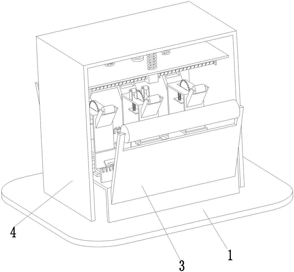

Image

  • Efficient processing equipment for silicon steel sheet of power transformer
  • Efficient processing equipment for silicon steel sheet of power transformer
  • Efficient processing equipment for silicon steel sheet of power transformer

Examples


Embodiment Construction

[0021] In order to make the technical means, creative features, goals and effects achieved by the present invention easy to understand, the present invention will be further described below in conjunction with specific illustrations.

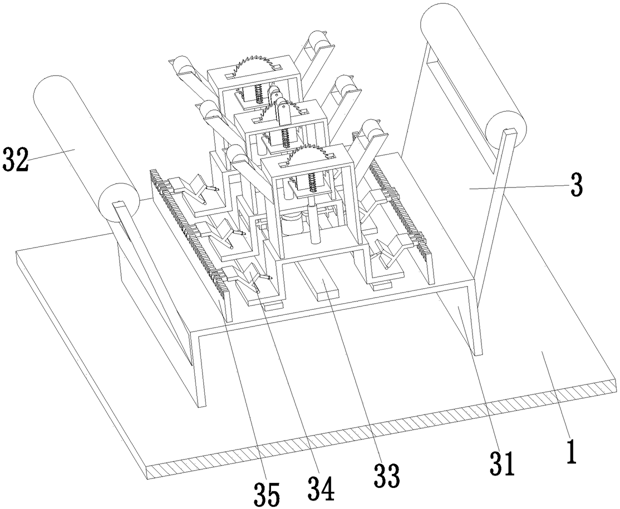
[0022] Such as Figure 1 to Figure 4 As shown, a power transformer silicon steel sheet high-efficiency processing equipment includes a bottom plate 1, an adjustable cutting device 3 is installed in the middle of the upper end of the bottom plate 1, and a cutting auxiliary device 4 is installed on the bottom plate 1, and the cutting auxiliary device 4 is installed on the bottom of the adjustable cutting device 3. Directly above, the cutting auxiliary device 4 can improve the stability of silicon steel sheet cutting during work.

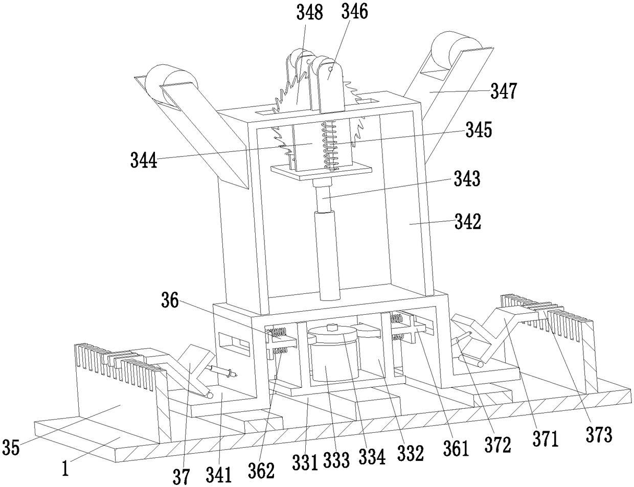
[0023] Described adjustment cutting device 3 comprises being installed on cutting support frame 31, and cutting support frame 31 is provided with two cutting guide rollers 32, and two cutting guide rollers 32 are symmetr...


PUM


Abstract

The invention relates to efficient processing equipment for a silicon steel sheet of a power transformer. The efficient processing equipment comprises a bottom plate, wherein a winding device is mounted on the bottom plate; a regulating cutting device is mounted on the middle part of the upper end of the bottom plate; an auxiliary cutting device comprises an auxiliary supporting frame mounted on the bottom plate; an auxiliary telescopic air cylinder is mounted on the inner wall of the auxiliary supporting frame; and the top end of the auxiliary telescopic air cylinder is mounted on an auxiliary lifting plate through a flange. The efficient processing equipment solves the problems that in an existing cutting process for a three-dimensional roll-core transformer silicon steel sheet, labor power is needed for cutting the silicon steel sheet through a cutting tool, cutting precision is poor, the position of the cutting tool needs to manually regulate for cutting silicon steel sheets of different specifications, precision of manually regulating the cutting tool is poor, the service life of the three-dimensional roll-core transformer is affected, and the like.

Description

technical field [0001] The invention relates to the technical field of power transformers, in particular to high-efficiency processing equipment for silicon steel sheets of power transformers. Background technique [0002] The three-dimensional wound core transformer is an energy-saving power transformer, which creatively reforms the laminated magnetic circuit structure and three-phase layout of the traditional power transformer, making the product performance more optimized, such as the three-phase magnetic circuit is completely symmetrical, oil-immersed Three-dimensional wound core transformer, oil-immersed three-dimensional wound core transformer, remarkable power saving effect, greatly reduced noise, stronger heat dissipation and overload capacity, compact structure and small size, etc., three-dimensional wound core transformer, three-dimensional combined wound core transformer, three-dimensional Combined three-phase wound core transformers, triangular three-dimensional ...

Claims


Application Information

Patent Timeline
Patent Type & Authority Applications(China)
IPC IPC(8): B23D45/06B23D45/10B23D47/04B23D47/02H01F41/02
CPCB23D45/003B23D45/068B23D45/10B23D47/02B23D47/04H01F41/0233
Inventor 陈秀兰
Owner 陈秀兰
Learn More