Plastic foam conveying device

A delivery device and plastic foam technology, applied in the field of plastic foam production, can solve problems such as sticking, troublesome operation, and operator respiratory tract infection

Active Publication Date: 2018-09-07
遵义锦鸿富科技发展有限公司
View PDF4 Cites 0 Cited by
  • Summary
  • Abstract
  • Description
  • Claims
  • Application Information

AI Technical Summary

Problems solved by technology

[0003] The first technical problem: due to the light weight of the plastic foam particles, the plastic foam particles are easily blown away by the outside wind during transportation, causing the plastic foam to splash around, and the operator walking back and forth around the conveyor belt is easy to drive the falling on the ground. The plastic foam particles are splashed. During the splashing process, on the one hand, the plastic foam particles falling on the ground will drive the dust on the ground, which will affect the surrounding environment. On the other hand, it is easy to cause the operator's respiratory tract infection and other diseases;
[0004] The second technical problem: During the transportation process of the conveyor belt, the plastic foam particles are easy to generate frictional static electricity with the surface of the conveyor belt, so that the plastic foam particles stick to the conveyor belt, and finally, it will cause waste of raw materials, and the conveyor belt needs to be cleaned manually. troublesome operation

Method used


Image

  • Plastic foam conveying device

Examples


Embodiment Construction

[0019] Further detailed explanation through specific implementation mode below:

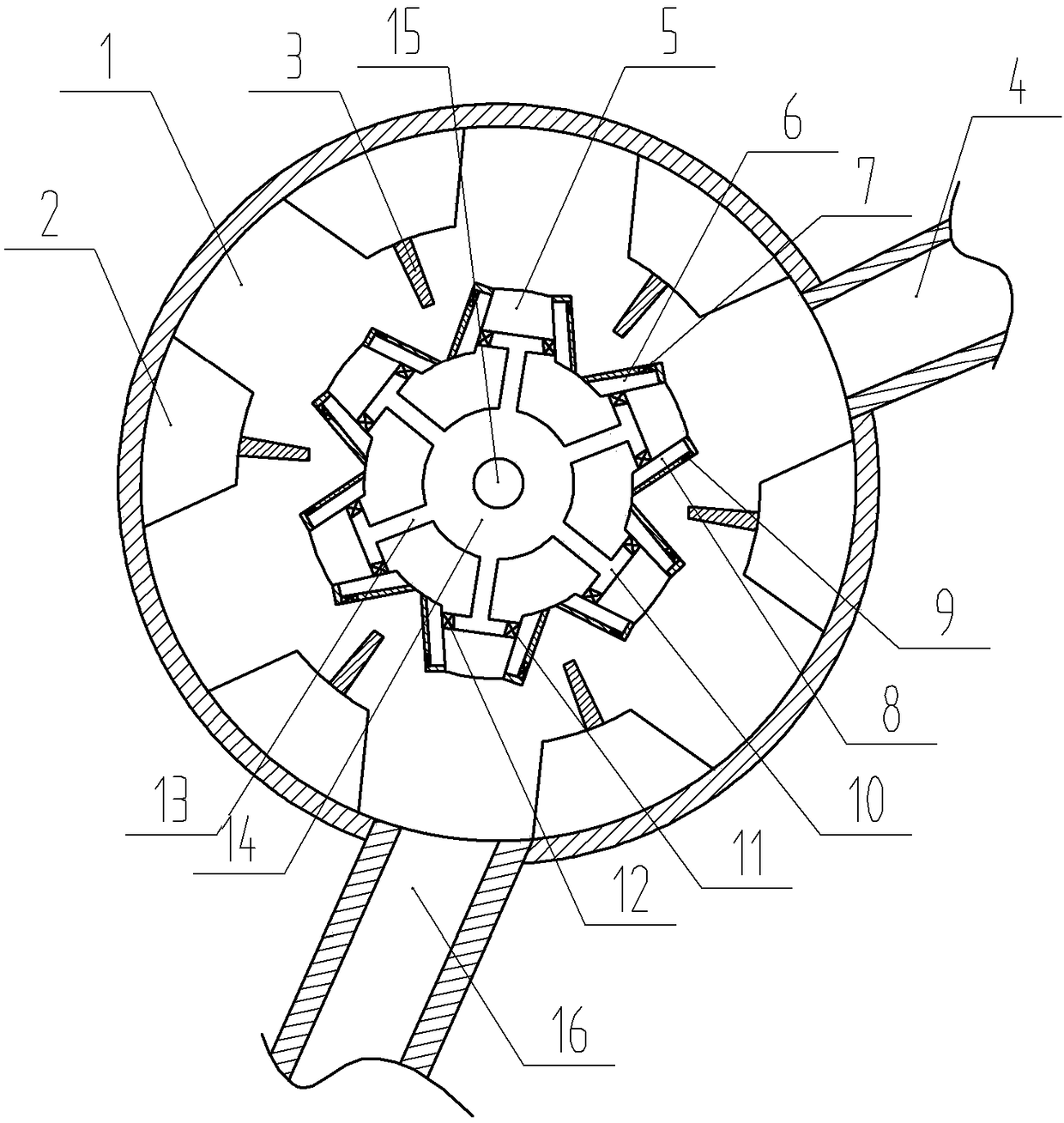
[0020] The reference signs in the drawings of the description include: transport shell 1, fixed teeth 2, spring leaf 3, feed pipe 4, gear 5, first compression chamber 6, first pressure valve 7, second compression chamber 8, second Pressure valve 9, branch pipe 10, first one-way valve 11, second one-way valve 12, main pipe 13, water tank 14, rotating shaft 15, discharge pipe 16.

[0021] The technical solutions of the present invention will be clearly and completely described below in conjunction with the accompanying drawings. Apparently, the described embodiments are some of the embodiments of the present invention, but not all of them. Based on the embodiments of the present invention, all other embodiments obtained by persons of ordinary skill in the art without making creative efforts belong to the protection scope of the present invention.

[0022] In the description of the present inventio...


PUM


Abstract

The invention discloses a plastic foam conveying device. The plastic foam conveying device comprises a transportation shell of a round hollow structure; a feeding pipe communicating with the transportation shell is arranged on the upper portion of the transportation shell; a plurality of fixed teeth are arranged on the inner wall of the transportation shell and each are provided with a leaf springfacing the center of the transportation shell; the center of the transportation shell is provided with a gear of a hollow structure; a motor allowing the gear to rotate is arranged outside the transportation shell; the gear is provided with a plurality of outer teeth which face the position between the adjacent fixed teeth and are of a hollow structure; a branch pipe is arranged inside each outertooth; the two sides of each outer tooth are correspondingly provided with a first compression cavity and a second compression cavity which communicate with the corresponding branch pipe; the first compression cavities and the second compression cavities can abut against the leaf springs; each first compression cavity is provided with a first pressure valve; each second compression cavity is provided with a second pressure valve; the gear is internally provided with an annular water tank; and the peripheral side of the water tank is provided with a main pipeline communicating with the branchpipes. Splashing is avoided, and plastic foam particles are conveniently transported.

Description

technical field [0001] The invention belongs to the technical field of plastic foam production, in particular to a plastic foam delivery device. Background technique [0002] Plastic foam is processed from raw material powder into foam particles of different quality through a foaming machine, and then processed and shaped by a mold at one time, and finally round or oval plastic foam particles are obtained. However, during the transportation of its plastic foam particles, conveyor belts are usually used for transmission, so there are the following technical problems: [0003] The first technical problem: due to the light weight of the plastic foam particles, the plastic foam particles are easily blown away by the outside wind during transportation, causing the plastic foam to splash around, and the operator walking back and forth around the conveyor belt is easy to drive the falling on the ground. The plastic foam particles are splashed. During the splashing process, on the ...

Claims


Application Information

Patent Timeline
IPC IPC(8): B65G53/16
CPCB65G53/16
Inventor 申天玖
Owner 遵义锦鸿富科技发展有限公司
Why Eureka
Try Eureka