Supercharge Your Innovation With Domain-Expert AI Agents!

Turbulent flow ignition needle

An ignition needle and turbulent flow technology, applied in the field of turbulent ignition needles, can solve the problems of gas waste, rising gas concentration in gas holes, ignition failure, etc., and achieve the effects of improving the ignition success rate, increasing the success rate and reducing the flow rate.

Inactive Publication Date: 2018-09-07
宁波金名片能源科技有限公司
View PDF5 Cites 1 Cited by
  • Summary
  • Abstract
  • Description
  • Claims
  • Application Information

AI Technical Summary

Problems solved by technology

When the mixed gas of gas and air is ejected from the small hole of the combustion plate, it has a certain pressure and the flow velocity is fast. The impulse generated when the mixed gas is ejected will often blow out the spark generated by the ignition needle and cause ignition failure. , which is one of the main reasons for the ignition failure rate of the existing ignition needle. Multiple ignition failures will not only cause waste of gas, but also cause the concentration of gas around the gas hole to increase and may cause deflagration, which has certain safety hazards. Therefore, , the structure of the existing ignition needle needs to be further improved

Method used


Image

  • Turbulent flow ignition needle
  • Turbulent flow ignition needle
  • Turbulent flow ignition needle

Examples


Embodiment Construction

[0021] The present invention will be further described in detail below in conjunction with the accompanying drawings and embodiments.

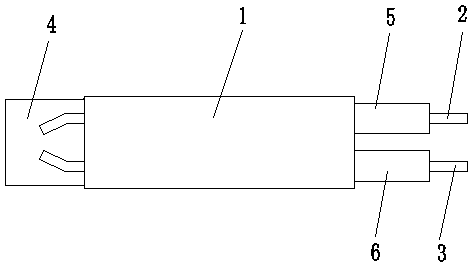
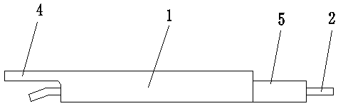
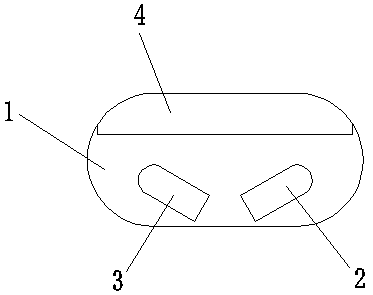
[0022] Such as Figure 1 to Figure 4 Shown is the structural representation of the present invention,

[0023] The reference signs therein are: ignition needle main body 1, positive electrode rod 2, negative electrode rod 3, baffle plate 4, positive electrode protective cover 5, negative electrode protective cover 6.

[0024] Such as Figure 1 to Figure 4 as shown,

[0025] A turbulent flow ignition needle, comprising an ignition needle main body 1, the ignition needle main body 1 is pierced to have a positive electrode rod 2 and a negative electrode rod 3, and the heads of the positive electrode rod 2 and the negative electrode rod 3 both extend from the head of the ignition needle main body 1 It can be seen that the tails of the positive pole 2 and the negative pole 3 protrude from the tail of the ignition needle body 1, and the ignition ...


PUM


Abstract

The invention discloses a turbulent flow ignition needle. The turbulent flow ignition needle comprises an ignition needle main body, wherein a positive electrode rod and a negative electrode rod penetrate through the ignition needle main body; the heads of the positive electrode rod and the negative electrode rod penetrate through the head of the ignition needle main body; the tail parts of the positive electrode rod and the negative electrode rod stretch out from the tail part of the ignition needle main body; a baffle plate is arranged at a part, located at the rear sides of the heads of thepositive electrode rod and the negative electrode rod, on the ignition needle main body; the head of the positive electrode rod is bent toward the side of the negative electrode rod; the head of thenegative electrode rod is bent toward the side of the positive electrode rod. The turbulent flow ignition needle disclosed by the invention has the advantages of simple structure and convenience for manufacturing; the baffle plate is arranged at the rear sides of the heads of the positive electrode rod and the negative electrode rod so that the flow speed of high-speed mix gas flow sprayed out from a fuel gas hole can be reduced in an ignition process; furthermore, the heads of the positive electrode rod and the negative electrode rod are bent toward the inner side, the distance between the heads of the positive electrode rod and the negative electrode rod is shortened and the success rate of ignition can be effectively improved.

Description

technical field [0001] The invention relates to the technical field of gas ignition, in particular to a turbulent flow ignition needle. Background technique [0002] At present, most of the gas stoves on the market use the ignition needle to ignite the gas. The ignition direction of the ignition needle is generally towards the ignition hole of the gas stove. The electric potential breaks down the air between the metal near the ignition hole and forms an electric spark, thus igniting the gas ejected from the gas hole. [0003] At present, in order to improve the combustion efficiency of gas, some gas stoves use pre-mixing of gas and air before burning, so as to achieve the purpose of saving energy. When the mixed gas of gas and air is ejected from the small hole of the combustion plate, it has a certain pressure and the flow velocity is fast. The impulse generated when the mixed gas is ejected often blows out the spark generated by the ignition needle, resulting in ignition ...

Claims


Application Information

Patent Timeline
Patent Type & Authority Applications(China)
IPC IPC(8): F24C3/10
CPCF24C3/103
Inventor 唐一波
Owner 宁波金名片能源科技有限公司
Features
  • R&D
  • Intellectual Property
  • Life Sciences
  • Materials
  • Tech Scout
  • Unparalleled Data Quality
  • Higher Quality Content
  • 60% Fewer Hallucinations
Learn More