
Solar light condensation heat collecting system and method

A solar energy concentrating and solar energy technology, applied in the field of solar energy utilization, can solve the problems such as the inability of the dish-type heat collector to achieve vacuum insulation, the inability to realize small-scale distributed energy applications, and the large cosine loss of the trough-type heat collector, and to avoid the Inability to collect heat in vacuum, avoid small-scale application of towers, and improve the effect of mirror field utilization

Pending Publication Date: 2018-09-07
河北珠峰仪器仪表设备有限公司
View PDF7 Cites 2 Cited by
  • Summary
  • Abstract
  • Description
  • Claims
  • Application Information

AI Technical Summary

Problems solved by technology

At present, the solar concentrating heat collectors are mainly trough type, dish type, linear Fresnel type and tower type, but each method has its own disadvantages, the general cost is high, the cosine loss of the trough type heat The ratio is limited, and the cost of the single curved reflector is high; the disc heat collector cannot achieve vacuum insulation, the heat loss is serious, and the cost of the hyperboloid reflector is high; the concentration ratio of the linear Fresnel heat collector is limited; the tower type is suitable for large Large-scale power station applications cannot realize small-scale distributed energy applications

Method used


Image

  • Solar light condensation heat collecting system and method
  • Solar light condensation heat collecting system and method
  • Solar light condensation heat collecting system and method

Examples


Embodiment 1

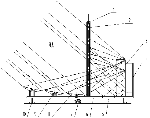
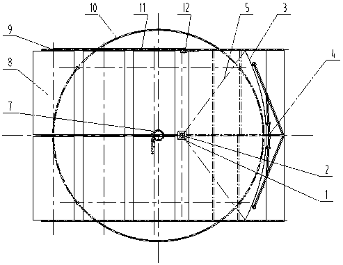
[0028] A solar energy concentrating heat collection system at least includes a heat collector 1, a vertical reflector group 3, a chassis 6, a chassis drive mechanism 7, a Fresnel reflector group 8, a bearing seat 9, a circular guide rail 10, and a rotating connecting rod 11 , connecting rod drive mechanism 12 and solar control unit;

[0029] The vertical reflector group 3 is a reflector around the heat collector 1, arranged towards the sun, the axis of the vertical reflector group 3 is parallel to the central axis of the heat collector 1, and the vertical reflector group 3 is used to reflect the incident light of the sun to the heat-absorbing surface of the collector 1;

[0030] The Fresnel reflector group 8 is on the other side of the heat collector 1, and is used to condense and reflect the sunlight on the other side of the heat collector 1 to the heat-absorbing surface of the heat collector 1; the Fresnel reflector group 8 The highest point will not affect the heat-absorbi...

Embodiment 2

[0034] Such as Figure 1A and Figure 1B As shown, a solar energy concentrating heat collection system is characterized in that it includes at least a heat collector 1, a heat collector bracket 2, an upright mirror group 3, an upright mirror group bracket 4, a bottom plane mirror group 5, and a chassis 6. Chassis driving mechanism 7, Fresnel mirror group 8, bearing housing 9, circular guide rail 10, rotating connecting rod 11, connecting rod driving mechanism 12 and solar control unit; the plane mirror used in erecting mirror group 3, The size of the upright mirror group 3 can be selected to be 12 meters high and 0.5 meter wide. The bracket 4 of the erected reflector group is fixed, the horizontal tangent of the erected reflector group 3 is an approximate parabola, the equation of the parabola is y²=2px, the focal length is set to 25 meters, and the opening of the parabola is 100 meters; one heat collector is a 4-meter-long vacuum heat collector The height is 24 meters in ser...

Embodiment 3

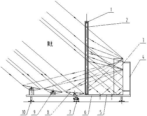
[0037] Such as Figure 2A and Figure 2B As shown, a solar energy concentrating heat collection system at least includes a heat collector 1, a heat collector support 2, an upright reflector group 3, an upright reflector group support 4, a bottom plane reflector group 5, a chassis 6, and a chassis drive Mechanism 7, Fresnel mirror group 8, bearing housing 9, circular guide rail 10, rotating connecting rod 11, connecting rod driving mechanism 12 and solar control unit; erecting mirror group 3 adopts a height of 3 meters (multi-block splicing height) A flat mirror with a width of 1 meter and a thickness of 1mm is cold-formed, and a thick aluminum liner is attached to the back. The thickness of the thick aluminum liner is between 1mm-1.5mm. Then the composition is arranged, the horizontal tangent line of the vertical reflector group 3 is a parabola, and the mirror surface is arranged on the chassis 6 facing the sun, the vertical reflector group 3 is fixed with the vertical reflec...


PUM


Abstract

The invention relates to a solar light condensation heat collecting system and method. The system at least comprises a heat collector, a vertical reflecting mirror assembly, a chassis, a chassis driving mechanism, a Fresnel reflecting mirror assembly, a bearing base, a circular guide rail, a rotating connecting rod, a connecting rod driving mechanism and a solar control unit; the vertical reflecting mirror assembly is a reflecting mirror arranged around the heat collector and is arranged towards the sun, the axis of the vertical reflecting mirror assembly is parallel to the central axis of theheat collector, and the vertical reflecting mirror assembly is used for reflecting incident light of the sun to the heat absorption face of the heat collector; the Fresnel reflecting mirror assemblyis arranged on the other side of the heat collector and used for concentrating and reflecting sunlight on the other side of the heat collector to the heat absorption face of the heat collector; the highest point of the Fresnel reflecting mirror assembly can not influence the process that the sunlight is projected to the heat absorption face of the heat collector; and the Fresnel reflecting mirrorassembly is arranged on the other side of the heat collector and used for concentrating and reflecting sunlight on the other side of the heat collector to the heat absorption face of the heat collector. The solar light condensation heat collecting system has the characteristics of being low in cost and high in efficiency and concentration ratio.

Description

technical field [0001] The invention belongs to the field of solar energy utilization, and in particular relates to a solar energy concentrating and heat collecting system and method. Background technique [0002] The development of human society is accompanied by the utilization of energy. With the depletion of traditional fossil energy and other non-renewable energy reserves and the deterioration of environmental pollution, solar energy, as an endless clean energy, has attracted more and more attention from the society. [0003] In order to improve the utilization efficiency of solar energy, it is necessary to optimize the structure of concentrating solar collectors. At present, the solar concentrating heat collectors are mainly trough type, dish type, linear Fresnel type and tower type, but each method has its own disadvantages, the general cost is high, the cosine loss of the trough type heat The ratio is limited, and the cost of the single curved reflector is high; the...

Claims


Application Information

Patent Timeline
Patent Type & Authority Applications(China)
IPC IPC(8): F24S23/70F24S30/422F24S50/20
CPCY02E10/47
Inventor 潘亚强史修瀚李波涛魏丽芬
Owner 河北珠峰仪器仪表设备有限公司
Learn More