System for collecting thermal energy of hot dry rock with U-shaped well and use method thereof

A technology of hot dry rock and underground heat exchange system, which is applied in the field of thermal energy development of dry hot rock, can solve problems such as unclear exploration, and achieve the effects of increasing heat conduction effect, reducing overall cost, and high heat exchange efficiency

Pending Publication Date: 2018-09-07
山东达尔玛新能源科技有限公司
View PDF10 Cites 2 Cited by
  • Summary
  • Abstract
  • Description
  • Claims
  • Application Information

AI Technical Summary

Problems solved by technology

However, there is no report on the application of spiral grooved pipes to hot dry rock thermal energy development technology, and the exploration in this field is still unclear

Method used


Image

  • System for collecting thermal energy of hot dry rock with U-shaped well and use method thereof
  • System for collecting thermal energy of hot dry rock with U-shaped well and use method thereof

Examples


Embodiment 1

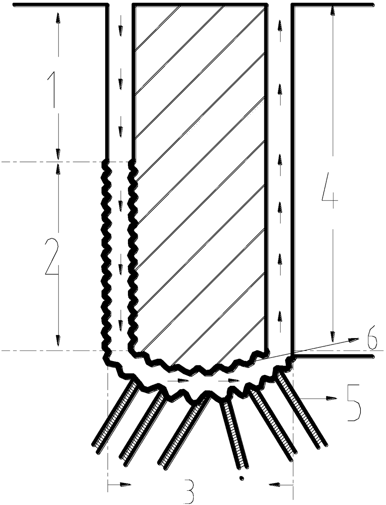
[0031] A system for collecting thermal energy of dry hot rock through a U-shaped well. The system for collecting thermal energy of dry hot rock is in the form of a "U"-shaped passage as a whole, including an injection casing and its insulation system 1, a cascaded heating system for rock heat utilization 2, and a long conductor Cheng swirling self-flushing underground heat exchange system 3, collection well casing and its insulation system 4, rock heat utilization cascade heating system 2 and injection casing and its insulation system 1 are connected together to form a "U"-shaped left vertical In the straight part, the rock heat utilization cascade heating system 2 and the injection casing and its insulation system 1 are located in the vertical shaft section of the connecting well, and the rock heat utilization cascade heating system 2 is set directly below the injection casing and its insulation system 1. The heat utilization cascade heating system 2 is connected with the inje...

Embodiment 2

[0039] In the thermal storage structure with low heat flow value and rock thermal conductivity, the system for collecting heat energy of dry rock through U-shaped wells is used. The system for collecting heat energy of dry rock is in the form of a "U"-shaped path as a whole, including injection casing and Its insulation system 1, rock heat utilization cascade heating system 2, long-lead swirl self-flushing underground heat exchange system 3, collection well casing and its insulation system 4, rock heat utilization cascade heating system 2 consists of array swirls It is formed by connecting self-flushing underground heat exchangers to form a rock heat utilization cascade heating system 2, which requires 25 sets of swirling self-flushing underground heat exchangers. The long-lead swirling self-flushing underground heat exchange system 3 is composed of groups of swirling self-flushing underground heat exchangers connected to form a long-lead swirling self-flushing underground heat...


PUM


Abstract

The invention relates to the technical field of hot dry rock thermal energy development, in particular to a system for collecting thermal energy of hot dry rock with a U-shaped well. The overall system for collecting the thermal energy of the hot dry rock with the U-shaped well is in a U-shaped channel and comprises an injection sleeve and heat preservation system of the injection sleeve, a rock heat utilization cascade heating system, a long-lead cyclone type self-flushing underground heat exchange system and a collecting well sleeve and heat preservation system of the collecting well sleeve.The rock heat utilization cascade heating system and the long-lead cyclone type self-flushing underground heat exchange system are each formed in the manner that a plurality of groups of cyclone typeself-flushing underground heat exchangers are connected. Each cyclone self-flushing underground heat exchanger is a spiral grooved tube. The system for collecting the thermal energy of the hot dry rock with the U-shaped well can be widely applied to enhancement type geothermal systems for hot dry rock thermal energy development and is low in cost, high in heat exchange efficiency and simple in system heat exchange cycle channel.

Description

technical field [0001] The invention relates to the technical field of hot dry rock thermal energy development, in particular to a system for collecting thermal energy of dry hot rock through a U-shaped well and an application method thereof. Background technique [0002] Medium and low temperature geothermal resources are mainly divided into hydrothermal type and dry hot rock type. At present, the hydrothermal type medium and low temperature geothermal mainly used by countries in the world only accounts for a very small part of the proven geothermal resources, while the medium and high temperature hot dry rock geothermal resources are rich in reserves and high in temperature on the earth. According to the latest data from relevant state departments, the total amount of hot dry rock resources at a depth of 3-10 kilometers in mainland my country is equivalent to 860 trillion tons of standard coal, and 2% can be mined, which is equivalent to the total national one-time energy ...

Claims


Application Information

Patent Timeline
Patent Type & Authority Applications(China)
IPC IPC(8): F24T10/20
CPCY02E10/10
Inventor 杨锐志张为廪
Owner 山东达尔玛新能源科技有限公司
Why Eureka
Try Eureka