Novel anti-disturbance shrinkage test device
A shrinkage test and anti-disturbance technology, which is applied in the direction of soil material testing and material inspection products, can solve the problems of inaccurate measurement of the horizontal deformation and disturbance of the sample, and achieve the convenience of use, increase the contact area, and ensure reliability sexual effect
- Summary
- Abstract
- Description
- Claims
- Application Information
AI Technical Summary
Problems solved by technology
Method used
Image
Examples
Embodiment 1
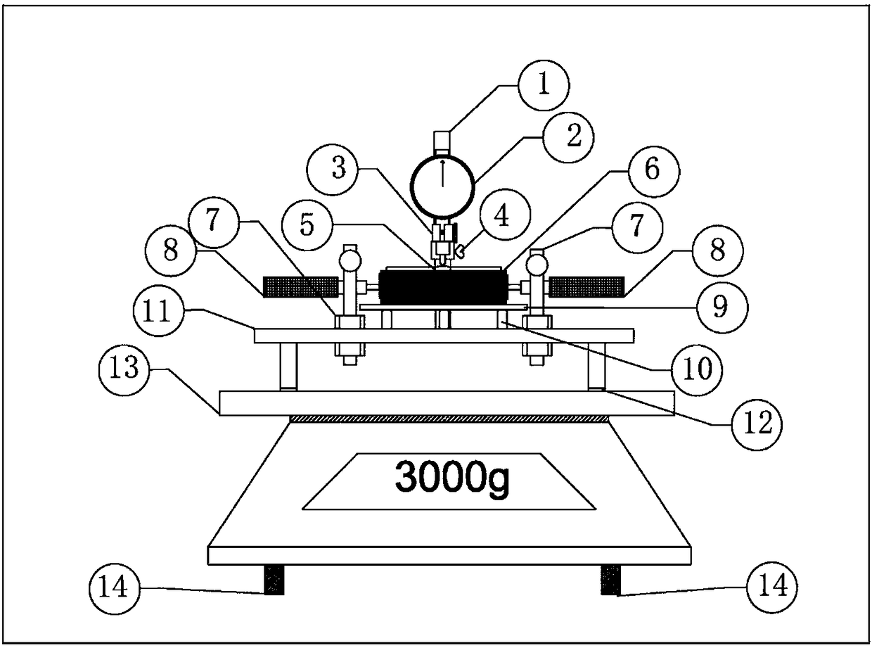
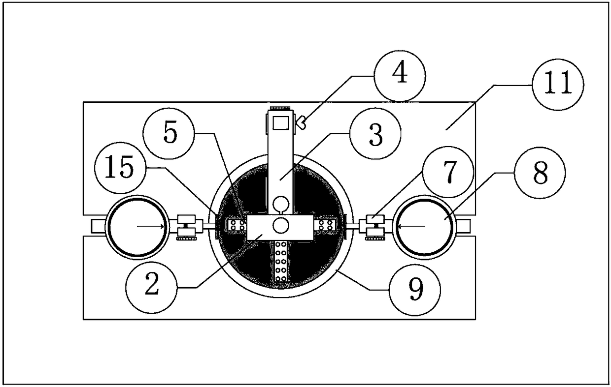
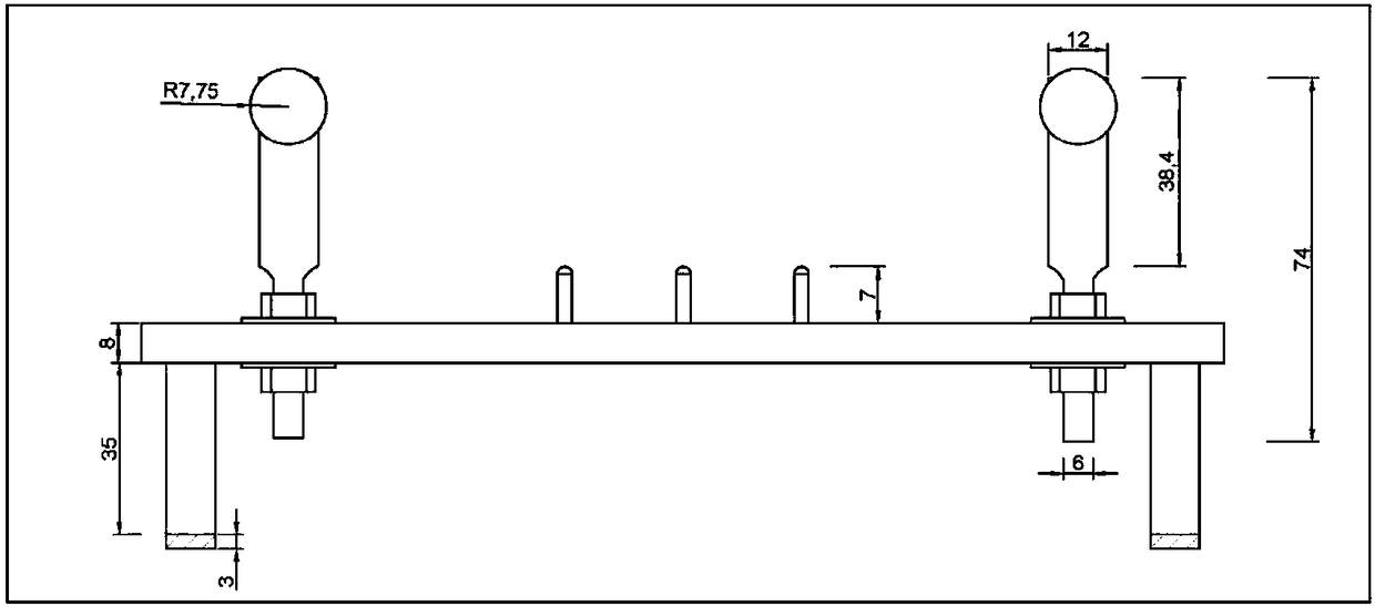
[0023] Such as Figure 1-6 As shown, an anti-interference shrinkage test device consists of a column brace (1), a vertical gauge (2), a beam (3), a limit collar (4), a vertical deformation measuring plate (5), a level, a measuring Table support (7), level gauge (8), perforated plate (9), spacer (10), base (11), rubber gasket (12), flat electronic scale (13), electronic scale level adjustment knob (14), the horizontal deformation measuring plate (15) is formed, except that the material of the base (11) is a hard plastic plate, the materials of other devices are all stainless steel; during the test, the column strut (1), the vertical scale ( 2), the beam (3), the limit collar (4) and the vertical deformation measuring plate (5) form a vertical deformation measurement device to measure the vertical shrinkage deformation of the sample; the horizontal gauge support (7) and horizontal gauge (8) form horizontal deformation measuring device; described panel electronic scale (13) and ...
Embodiment 2
[0025] Such as Figure 1-6 As shown, when carrying out the shrinkage test, at first the flat electronic scale (13) is kept level by the electronic scale level adjustment knob (14), and then the porous plate (9) with the groove is placed on a height of 11.5 mm and a radius of 1.5mm spacer (10), and insert the spacer into the groove of the perforated plate (9), place a cross-shaped measuring plate (5) with a wing width of 6mm on the top of the sample, and the thimble of the vertical gauge (2) against the At the center of the cross-shaped measuring board (5), the vertical meter (2) is connected with the column strut (1) through the beam (3), and the beam (3) and the column strut (1) will be further passed through after the preliminary connection The limit collar (4) limits the sliding of the beam (3). The level gauge (8) is connected to the base (11) through the support (7), and the connecting detail of the base (11) and the support (7) is a bolt combination structure, which can...
Embodiment 3
[0027] Such as Figure 2-7 As shown, if the test only needs to measure the vertical deformation, you can unscrew the nuts of the two horizontal scale supports (7) on either side of the base, and place the two supports (7) along the base (11) respectively. Move out the groove position to the left and right sides of the test instrument, then according to the relevant steps described in Example 2, operate in the order of the perforated plate (9), sample (6), and cross-shaped measuring plate (5), and finally Install the vertical meter (2) and adjust the measuring range, then keep the tablet electronic scale (13) level by the electronic scale level adjustment knob (14), and finally place the whole device on the tablet electronic scale (13), and start the test.
PUM
| Property | Measurement | Unit |
|---|---|---|
| length | aaaaa | aaaaa |
| diameter | aaaaa | aaaaa |
| length | aaaaa | aaaaa |
Abstract
Description
Claims
Application Information
 - R&D
- Intellectual Property
- Life Sciences
- Materials
- Tech Scout
- Unparalleled Data Quality
- Higher Quality Content
- 60% Fewer Hallucinations
Browse by: Latest US Patents, China's latest patents, Technical Efficacy Thesaurus, Application Domain, Technology Topic, Popular Technical Reports.
© 2025 PatSnap. All rights reserved.Legal|Privacy policy|Modern Slavery Act Transparency Statement|Sitemap|About US| Contact US: help@patsnap.com


