Eureka AIR delivers breakthrough ideas for toughest innovation challenges, trusted by R&D personnel around the world.

Motor and stator iron core thereof

A stator iron core and iron core technology, applied in electrical components, electromechanical devices, electric components, etc., can solve problems such as high cost and achieve the effect of low resistance

Inactive Publication Date: 2018-09-07
喻文斌
View PDF2 Cites 1 Cited by
  • Summary
  • Abstract
  • Description
  • Claims
  • Application Information

AI Technical Summary

Problems solved by technology

However, in the scheme of the above-mentioned literature, since the two adjacent iron core units are rotationally fitted, it is a pair of technical contradictions to ensure smooth rotation and no gap between the two. Of course, it can be solved by improving the machining accuracy. But high precision generally leads to high cost, so it is an urgent technical problem for those skilled in the art to solve the above problems by improving the structure

Method used


Image

  • Motor and stator iron core thereof
  • Motor and stator iron core thereof
  • Motor and stator iron core thereof

Examples


Embodiment 1

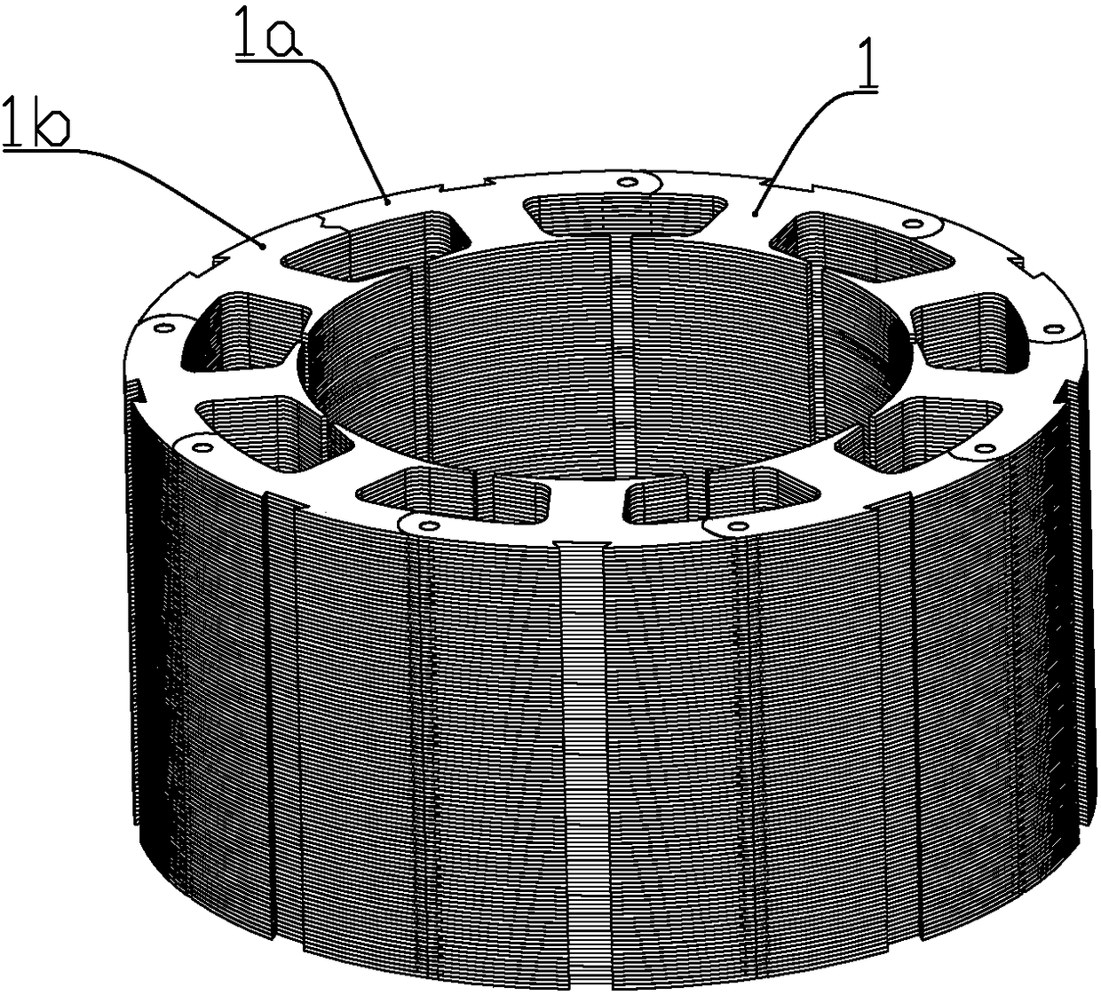
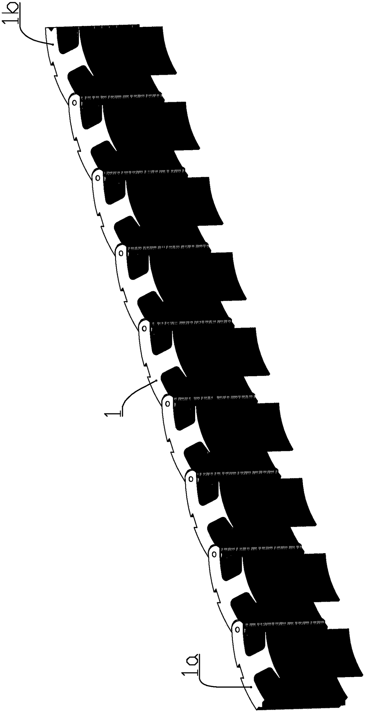
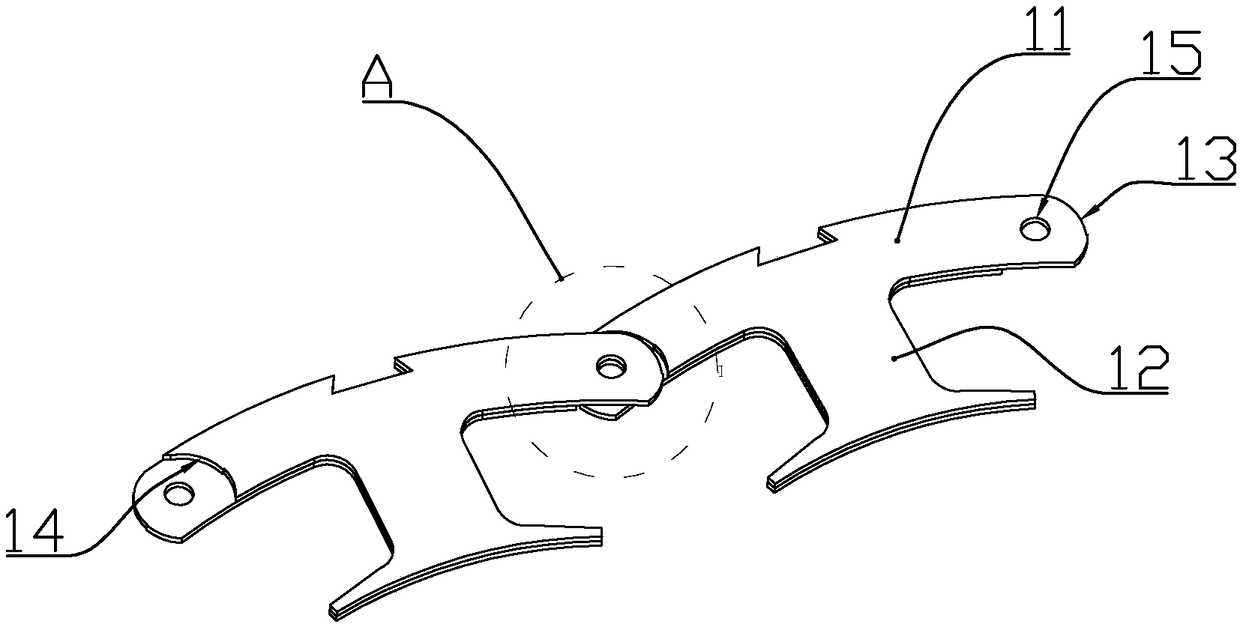
[0033] combine Figure 1 to Figure 6 As shown, this embodiment is a stator core of a motor, including a plurality of iron core layers spliced ​​together along the axial direction of the motor, each iron core layer includes a plurality of iron core units 1, and each iron core unit It includes a T-shaped yoke part 11 and a winding installation part 12 connected in the middle of the inner side of the yoke part, and the core units of each core layer can be formed into a ring shape by the yoke part.

[0034] One end of the yoke portion is a concave portion 14, and the other end is a convex portion 13, and the yoke portion is provided with a hinge portion on one side of the convex portion, and the concave portion and the convex portion of the core units of the adjacent two core layers Staggered arrangement; the hinge parts of left and right adjacent iron core units located on different iron core layers are rotationally connected.

[0035] The hinge part shown in the figure is a circu...

Embodiment 2

[0045] combine Figure 7 to Figure 8 As shown, this embodiment is a stator core of a motor, which includes a plurality of core groups spliced ​​together along the axial direction of the motor, and each core group includes 2-5 core groups spliced ​​together along the axial direction of the motor Iron core layer, each iron core layer includes a plurality of iron core units, each iron core unit includes a yoke iron part and a winding installation part connected in the middle of the inner side of the yoke iron part, the iron core unit of each iron core layer can The ring shape is surrounded by the yoke portion.

[0046] One end of the yoke part is a concave part, and the other end is a convex part, and the yoke part is provided with a hinge part on one side of the convex part, and the concave parts and convex parts of the core units of two adjacent core layers are alternately arranged ; The hinges of the left and right adjacent iron core units located on different iron core group...

Embodiment 3

[0053] This embodiment is a motor, including a stator and a rotor. The stator includes the stator core of the foregoing embodiment, and a winding wound on the stator core.


PUM


Abstract

The invention discloses a motor and a stator iron core thereof. The stator iron core comprises multiple iron core layers axially spliced together along the motor, each iron core layer comprises multiple iron core units, each iron core unit comprises a yoke part and a winding mounting part, and the iron core units of each iron core layer can surround a circle shape through the yoke part; one end ofthe yoke part is a concave part, and the other end is the convex part; a hinging part is arranged at convex part side on the yoke part, the concave parts and the convex parts of the iron core units of two adjacent iron core layers are staggered; the hinging parts of the left and right adjacent iron core units on different iron core layers are in rotary connection; the convex part sidewall is an arc part in circular arc, the circular arc diameter of the arc part is greater than the width of the yoke part, and the distance between the center of the arc part and the axis of the motor is less than the distance between the rotation center of the hinging part and the axis of the motor; and the sidewall shape of the concave pat is adapted to the sidewall shape of the convex part. The air gap canbe reduced on the basis of ensuring the convenient assembling and small rotation resistance, thereby reducing the leakage flux.

Description

technical field [0001] The invention belongs to the field of motors, and in particular relates to a stator core structure of the motor. Background technique [0002] The patent document whose document number is JP3379461B2 discloses a manufacturing method of a stator core, which includes punching out a part corresponding to the contour of the core material of the first core material in which a plurality of plate-shaped core materials are continuously arranged via the end face of the edge part. process; a plurality of plate-like chips are continuously arranged through the end faces of the edge portions, and the shape of the edge portions opposite to each other in the lamination direction is the same as that of the core of the first core member and the second punching device for punching the same A portion corresponding to the contour of each core member of each of the second core members to form the second core member, wherein the first punching device and the second punching...

Claims


Application Information

Patent Timeline
IPC IPC(8): H02K1/14
CPCH02K1/148H02K2213/03
Inventor 喻文斌
Owner 喻文斌
Why Eureka
Eureka Blog
Learn More