Power converter, and control circuit and circuit method thereof

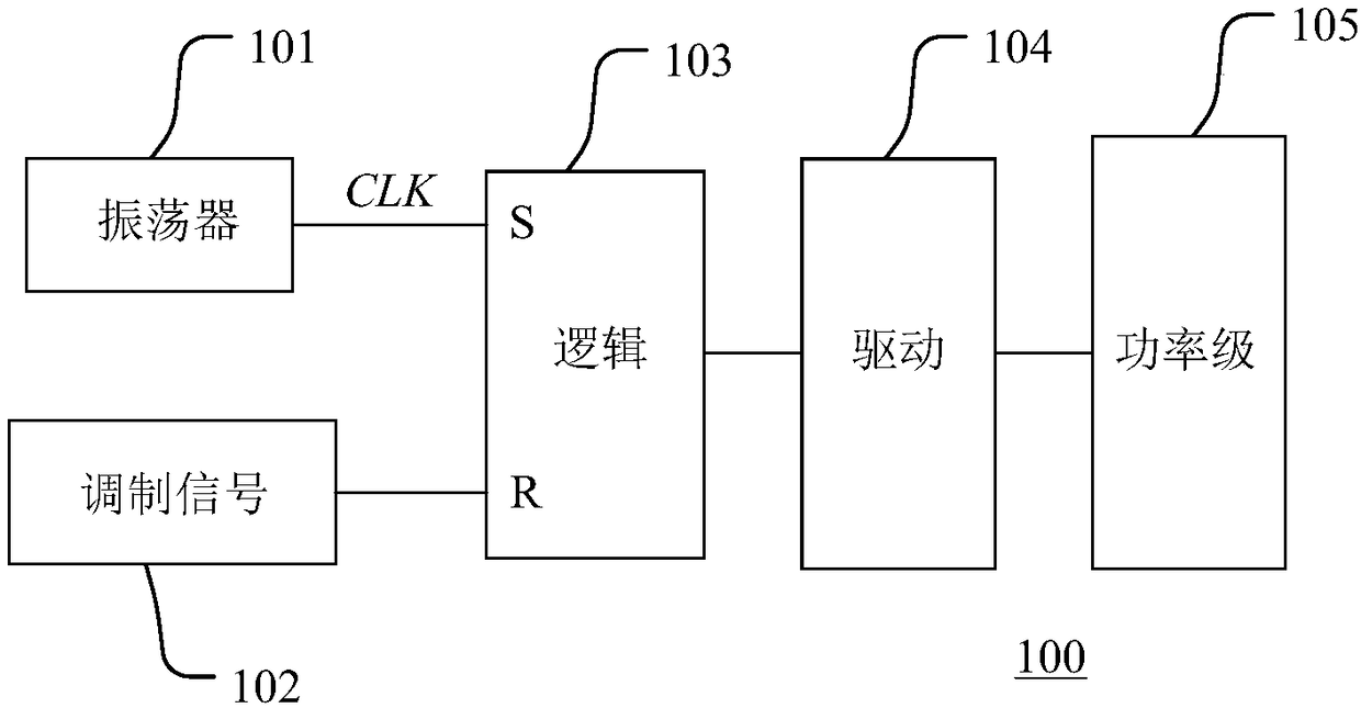
A technology for power converters and control circuits, which is applied to electrical components, electronic switches, pulse duration/width modulation, etc., can solve the problem that the buck converter 100 is difficult to achieve normal operation, etc.

Pending Publication Date: 2018-09-07
HANGZHOU SILAN MICROELECTRONICS
View PDF0 Cites 11 Cited by
  • Summary
  • Abstract
  • Description
  • Claims
  • Application Information

AI Technical Summary

Problems solved by technology

According to the volt-second balance theorem, in the BUCK topology, the duty cycle D of the system operation is equal to the ratio of the output voltage to the input voltage, so when the output voltage of the BUCK converter 100 is close t

Method used


Image

  • Power converter, and control circuit and circuit method thereof
  • Power converter, and control circuit and circuit method thereof
  • Power converter, and control circuit and circuit method thereof

Examples


Embodiment Construction

[0052] Various embodiments of the invention will be described in more detail below with reference to the accompanying drawings. In the various drawings, the same elements are denoted by the same or similar reference numerals. For the sake of clarity, various parts in the drawings have not been drawn to scale.

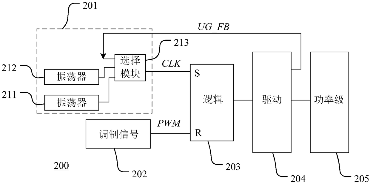
[0053] figure 2 A schematic block diagram of a power converter according to an embodiment of the invention is shown. Such as figure 2 As shown, the power converter 200 is, for example, a BUCK topology, including a control circuit and a main circuit. The control circuit includes a clock signal generation circuit 201 , a modulation signal generation circuit 202 , a logic module 203 , and a drive module 204 . The main circuit includes a power stage 205 .

[0054] The clock signal generating circuit 201 is used to generate a working clock signal CLK, and the working clock signal CLK controls the switching period of the switching control signal. In this embodiment, t...


PUM


Abstract

A power converter, and a control circuit and a circuit method thereof are disclosed. The power converter comprises a clock signal generation circuit, a modulation signal generation circuit, and a logic module which is connected with the clock signal generation circuit and the modulation signal generation circuit and used for generating an on-off control signal according to a working clock signal and a modulation signal, wherein when a ratio between an output voltage and an input voltage is less than a duty ratio corresponding to the working clock signal at a first frequency, the clock signal generation circuit controls the frequency of the working clock signal to be the first frequency, and when the ratio between the output voltage and the input voltage is greater than the duty ratio corresponding to the working clock signal at the first frequency, the clock signal generation circuit controls the frequency of the working clock signal to be a self-adaptive frequency. According to the power converter of the invention, through self-adaptive frequency reduction processing, turn-on time is adaptively prolonged in the case of ensuring certain minimum turn-off time, and the duty ratio ismaximized, thereby expanding the range of a working voltage and improving adjustable dynamic range of the output voltage.

Description

technical field [0001] The present invention relates to the field of switching power supplies, and more specifically, to a power converter and its control circuit and control method. Background technique [0002] With the advancement of circuit electronics technology, switching power supplies continue to develop in the direction of high power density, high efficiency, and high reliability. In switching power supplies of various electronic products, power converters are widely used. Power converters can adopt various topologies, such as BOOST, BUCK, BOOST-BUCK, and flyback topologies. During operation, the power converter uses PWM modulation (Pulse Width Modulation, pulse width modulation) to control the conduction state of the switch tube, thereby controlling the power transmission from the input end to the output end, so as to provide a stable output voltage and / or current. [0003] figure 1 A schematic block diagram of a BUCK converter circuit according to the prior art...

Claims


Application Information

Patent Timeline
IPC IPC(8): H03K17/567H03K7/08
CPCH03K7/08H03K17/567
Inventor 李伟王军宁志华
Owner HANGZHOU SILAN MICROELECTRONICS
Why Eureka
Try Eureka