Eureka AIR delivers breakthrough ideas for toughest innovation challenges, trusted by R&D personnel around the world.

Automatic balling machine for slide rail

An automatic and bead-loading technology, applied in assembly machines, metal processing, metal processing equipment, etc., can solve the problems of consuming a lot of time and energy in research and development, difficulty in mechanical automatic assembly design, etc., and achieve the effect of simple structure

Pending Publication Date: 2018-09-11
浙江进家五金有限公司
View PDF0 Cites 0 Cited by
  • Summary
  • Abstract
  • Description
  • Claims
  • Application Information

AI Technical Summary

Problems solved by technology

[0002] The material for ball loading on the slide rail includes the first ball, the second ball, the third ball and the base plate. The auxiliary plate is installed in advance on the base plate. The auxiliary plate has three continuous end faces that need to be filled with beads. The three end faces are laid out in a straight line. , so the design of mechanical automation assembly is difficult, it is difficult to process multiple parts at one time, and it takes a lot of time and energy to develop

Method used


Image

  • Automatic balling machine for slide rail
  • Automatic balling machine for slide rail
  • Automatic balling machine for slide rail

Examples


Embodiment Construction

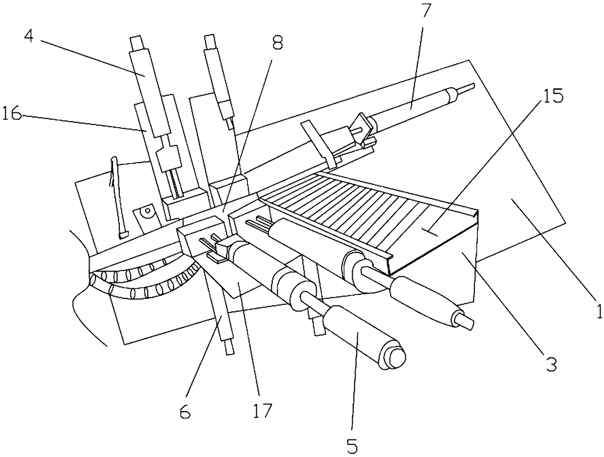
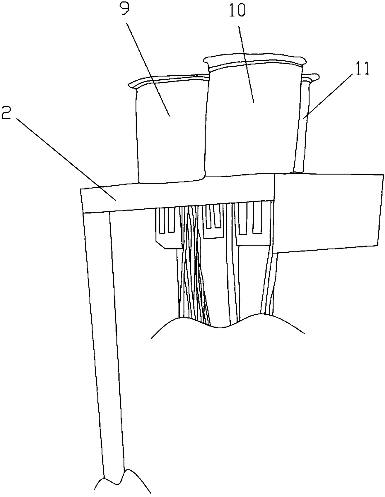
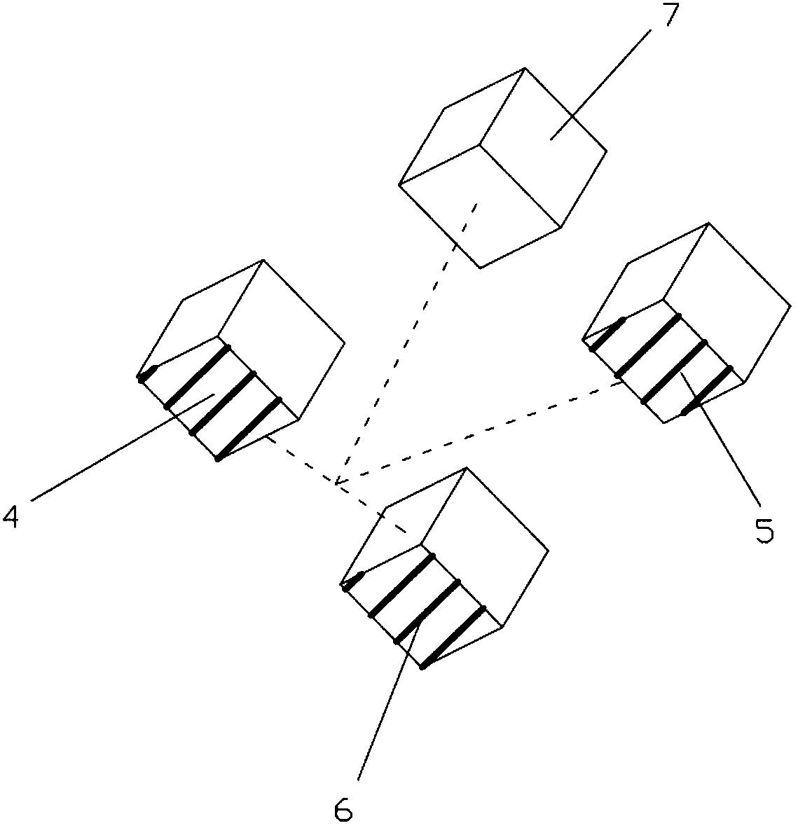
[0019] Such as Figure 1-Figure 4 As shown, a slide rail automatic bead loading machine includes a base frame 1, and the base frame 1 is provided with a supporting platform 2, a feeding platform 3, a first cylinder group 4, a second cylinder group 5, and a third cylinder group 6. The fourth cylinder group 7 and the mounting block 8, the support table 2 is provided with the first vibrating plate 9, the second vibrating plate 10 and the third vibrating plate 11, the first cylinder group 4, the second vibrating plate The piston rods of the cylinder group 5 and the third cylinder group 6 are fixedly connected with ejector rods, and the output direction between the first cylinder group 4 and the second cylinder group 5 and between the second cylinder group 5 and the third cylinder group 6 Perpendicular to each other, the piston rod of the fourth cylinder group 7 is provided with a push block, and the output direction of the fourth cylinder group 7 is respectively connected with the...


PUM


Abstract

The invention relates to automatic equipment for a slide rail, in particular to an automatic balling machine for a slide rail, and the automatic balling machine solves the automatic problem of slide rail balling. The automatic balling machine comprises a base frame, wherein a supporting table, a feeding table, a first air cylinder group, a second air cylinder group, a third air cylinder group, a fourth air cylinder group and a mounting block are arranged on the base frame; a first vibrating disc, a second vibrating disc and a third vibrating disc are arranged on the supporting table; ejector rods are fixedly connected on piston rods of the first air cylinder group, the second air cylinder group and the third air cylinder group; and the output direction between the first air cylinder groupand the second air cylinder group is mutually perpendicular to that between the second air cylinder group and the third air cylinder group. The automatic equipment is simple in structure, and realizesonce balling through matching between the vibrating discs and the air cylinder groups for pressing 12 balls into an auxiliary plate on a base plate once; and meanwhile, a pneumatic gun and a filter strip are arranged, so that a cavity path can be easily dredged by utilizing the tools while faults appear, and therefore, the automatic equipment has practicability and economical efficiency.

Description

technical field [0001] The invention relates to automatic equipment for slide rails, in particular to an automatic bead loading machine for slide rails. Background technique [0002] The material for ball loading on the slide rail includes the first ball, the second ball, the third ball and the base plate. The auxiliary plate is installed in advance on the base plate. The auxiliary plate has three continuous end faces that need to be filled with beads. The three end faces are laid out in a straight line. , so the design of mechanical automation assembly is difficult, and it is difficult to process multiple parts at the same time, which requires a lot of time and energy for research and development. Contents of the invention [0003] Aiming at the deficiencies in the existing technology, the invention provides an automatic bead loading machine for slide rails. [0004] In order to achieve the above object, the technical solution adopted by the present invention is: a slide...

Claims


Application Information

Patent Timeline
IPC IPC(8): B23P21/00B23P19/00B23P19/02
CPCB23P19/001B23P19/02B23P21/00
Inventor 贾鹏郑权华
Owner 浙江进家五金有限公司
Why Eureka
Eureka Blog
Learn More