

Gearbox grinding device
A technology of gear boxes and grinding discs, which is applied in the direction of grinding drive devices, grinding/polishing safety devices, grinding machines, etc., can solve the problems of low manual grinding efficiency and high risk factor, and achieve simplified preparation work, good grinding effect, and improved The effect of sanding
Inactive Publication Date: 2018-09-11
重庆市耀植机械有限责任公司
View PDF2 Cites 14 Cited by
- Summary
- Abstract
- Description
- Claims
- Application Information
AI Technical Summary
Problems solved by technology
[0003] The purpose of the present invention is to provide a gear box grinding device to solve the problems of low manual grinding efficiency and high risk factor
Method used
View moreImage
Smart ImageViewing Examples

Examples
Embodiment Construction
[0014] The present invention will be described in further detail below by means of specific embodiments:
Login to View More PUM
 Abstract
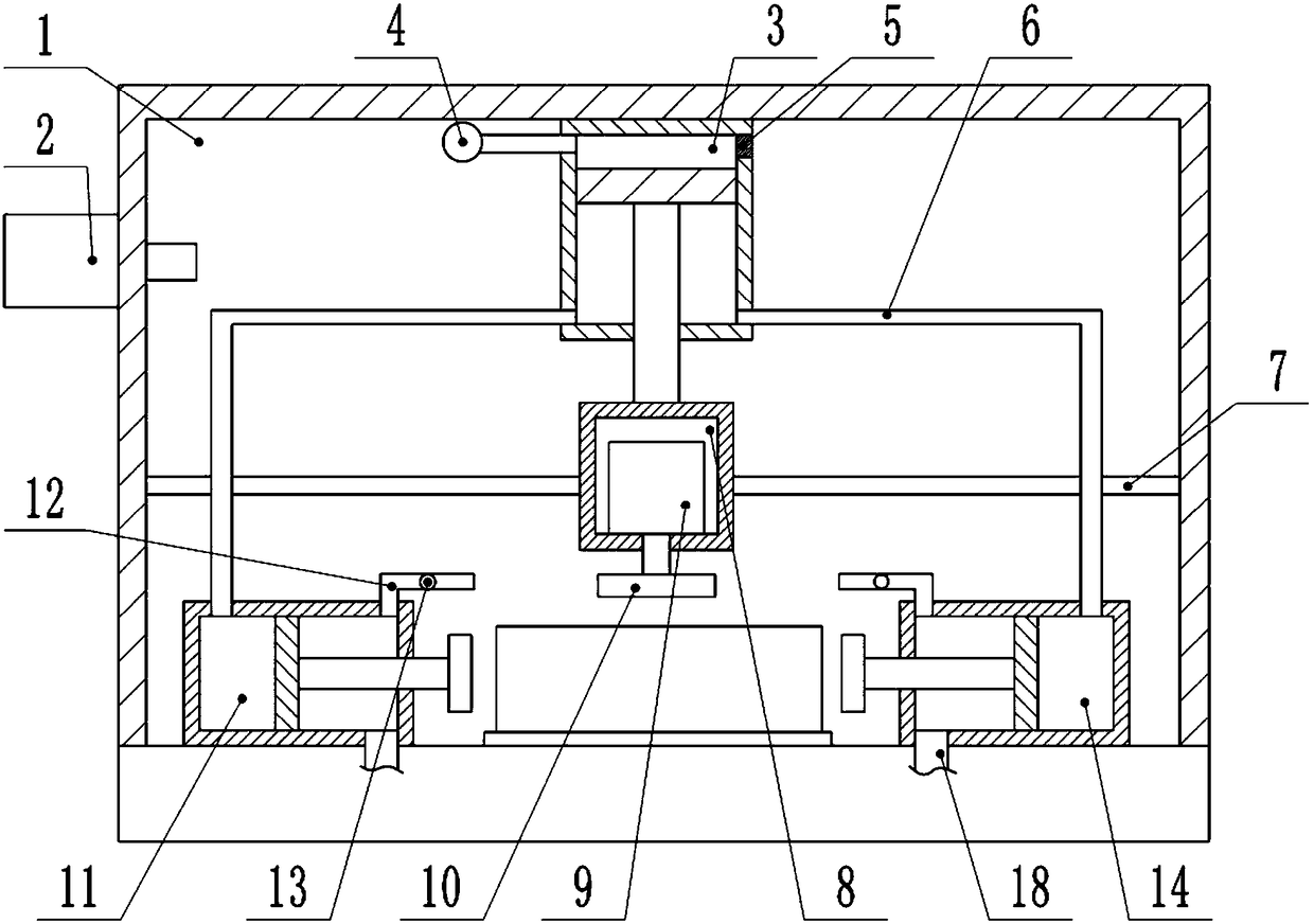
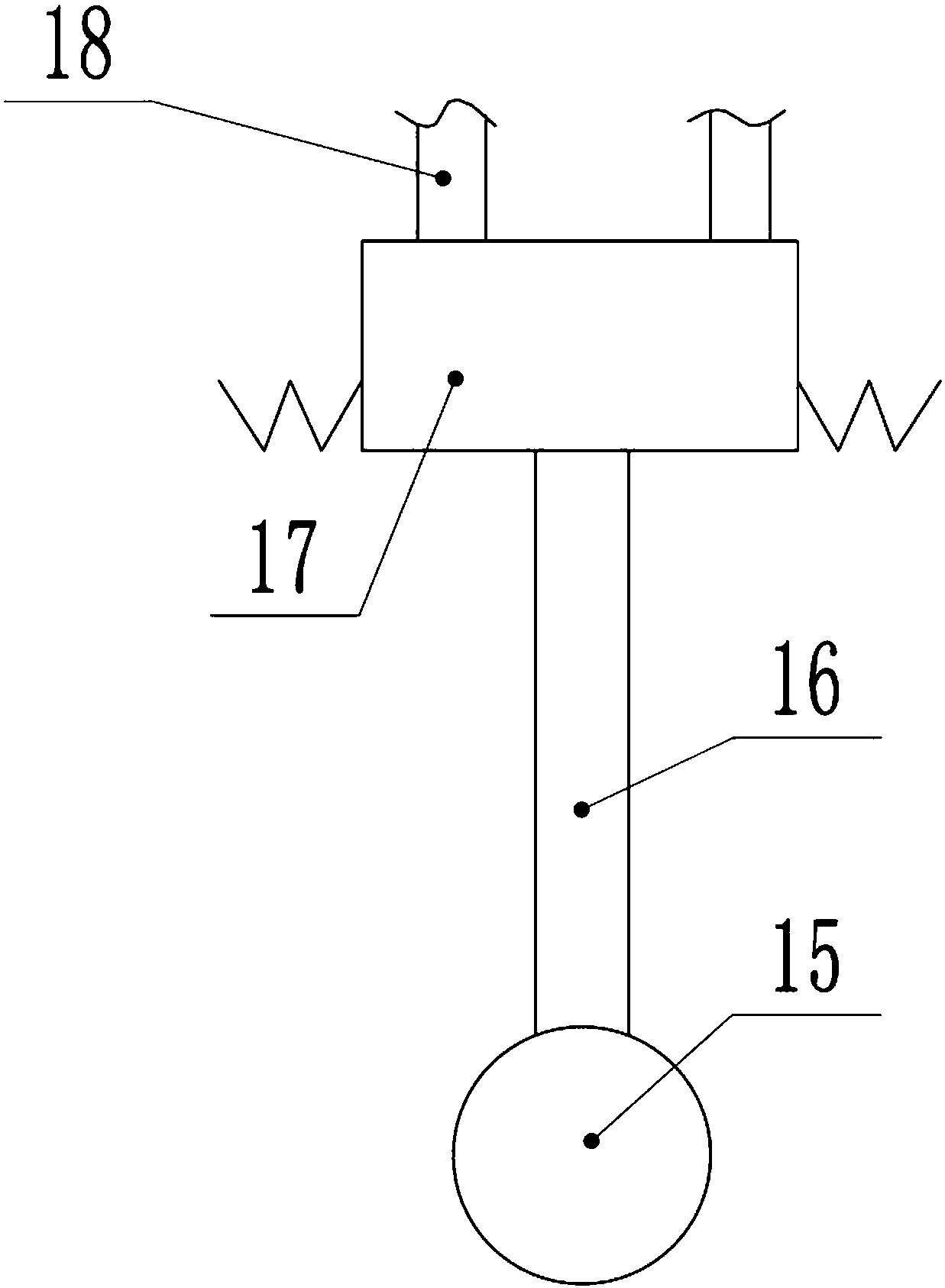
The invention belongs to the technical field of grinding equipment, and particularly discloses a gearbox grinding device. The gearbox grinding device comprises a workbench. A grinding box is arrangedon the workbench. A lifting air cylinder is arranged on the top wall of the grinding box. A motor is connected to the end of a piston rod of the lifting air cylinder. An output shaft of the motor is connected with a grinding disc. A first air cylinder and a second air cylinder are arranged on the workbench, and clamping discs are arranged on piston rods of the two air cylinders. The lifting air cylinder, the first air cylinder and the second air cylinder communicate with air pipes. A rodless cavity of the lifting air cylinder is connected with a first air pump. A second air pump is further included. A bidirectional valve is arranged at the air outlet end of the second air pump. Two branch pipes communicating with the first air cylinder and the second air cylinder correspondingly are connected to the bidirectional valve. Dust blowing pipes are arranged in the first air cylinder and the second air cylinder, and an electric valve is arranged in each dust blowing pipe. The air outlet endsof the dust blowing pipes are located below the grinding disc. A sliding plate is in sliding connection to the workbench and is located below the grinding disc. According to the scheme, automatic grinding of a gearbox is achieved, and meanwhile grinding dust can be treated.
Description
technical field [0001] The invention belongs to the technical field of grinding equipment, in particular to a gear box grinding device. Background technique [0002] Grinding refers to grinding or rubbing the surface of the workpiece to make the workpiece smooth and delicate. During the processing of the gearbox, the gearbox usually needs to be polished. In the prior art, the gear box is usually fixed on the workbench, and then the staff holds the grinding head or the grinding disc to grind the gear box. In this way, the qualified rate of grinding is low, the operator is prone to fatigue, and safety accidents are prone to occur. Moreover, the work is labor-intensive and the work risk factor is high; the dust is relatively large, which will cause health hazards to the workers. Contents of the invention [0003] The purpose of the present invention is to provide a gear box grinding device to solve the problems of low manual grinding efficiency and high risk factor. [0004...
Claims
Login to View More Application Information
Patent Timeline
 Patent Type & AuthorityApplications(China)
IPC IPC(8): B24B19/00B24B41/06B24B41/00B24B55/06B24B27/00B24B47/06
CPCB24B19/00B24B27/0015B24B41/005B24B41/06B24B47/06B24B55/06
Inventor钟志希
Owner重庆市耀植机械有限责任公司