Artificial stone wall panel

a technology of artificial stone and wall panels, applied in the field of artificial stone wall panels, can solve the problems of warpage and cracks not being able to be avoided during the construction, laborious and costly boards on the surface of an external wall, and great restrictions in construction and cost, so as to achieve the effect of simplifying preparation

Inactive Publication Date: 2008-05-13
DOPPEL
View PDF7 Cites 12 Cited by
  • Summary
  • Abstract
  • Description
  • Claims
  • Application Information

AI Technical Summary

Benefits of technology

[0016]In the invention of this application, it is possible to solve problems of the prior art, realize an external material excellent in terms of designing property with a natural texture by an artificial stone, maintain a predetermined strength for installation, and simplify preparation and work for installation onto an exterior wall surface.

Problems solved by technology

Although use of such siding boards improves a design of external walls and allows a variety in terms of selection of design, adhesion or connection of the engagement fittings through post treatment and installation of the boards onto a surface of an external wall were laborious and costly, and were great restriction factors in terms of construction and cost.
However, ordinary cement or ceramic sidings have been problematic in that, in such mold-integrating, warpage and cracks could not be avoided during cure shrinkage of these products.
However, such ALC panels and pre-cast concrete panels have an artificial appearance with little natural texture, and are also heavy in terms of weight.
Also, a shape and position of the fittings were characteristically restricted.
Nevertheless, in this case, only a simple mold-lamination process is attempted, and this molding method is limited.
Further, because a relationship between composition of a molded product and integration with a fitting has not been taken into consideration, occurrence of warpage and cracks following integration is not satisfactorily suppressed.
Moreover, design properties and physical properties such as strength for using this artificial stone as an external wall material is not actually taken into consideration.

Method used


Image

  • Artificial stone wall panel
  • Artificial stone wall panel
  • Artificial stone wall panel

Examples


example 1

[0065]Compositions shown in Table 1 were prepared. In this table, MMA indicates methyl methacrylate resin component, and additives indicate a peroxide-type curing catalyst and a light stabilizer.

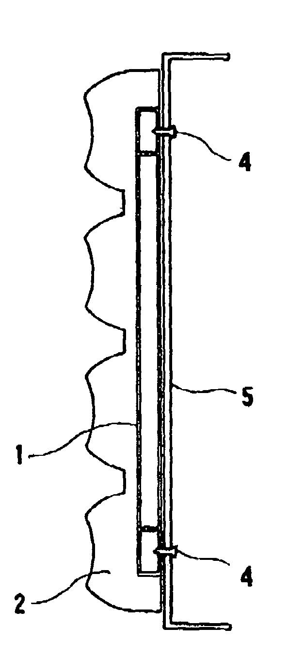
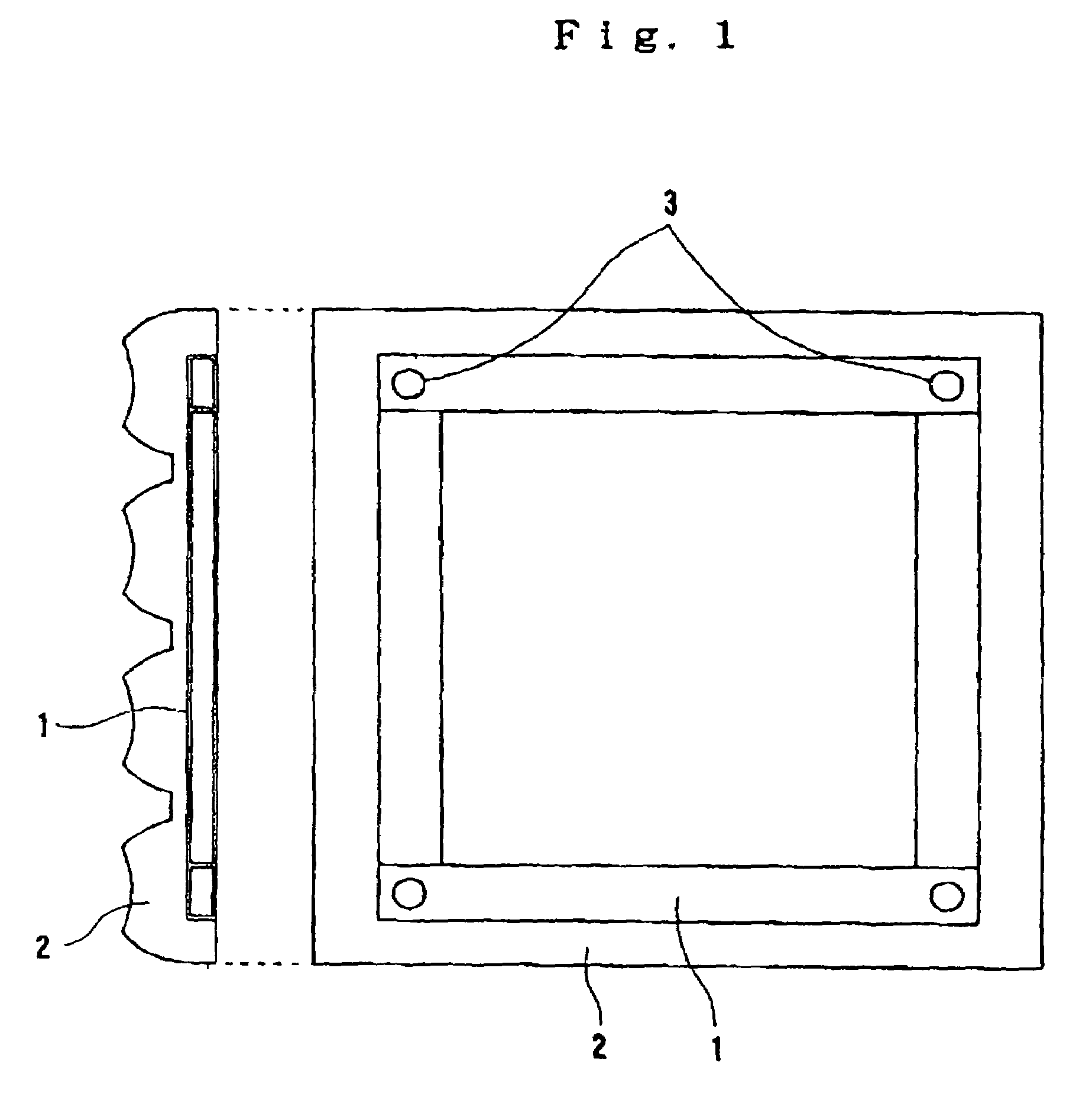
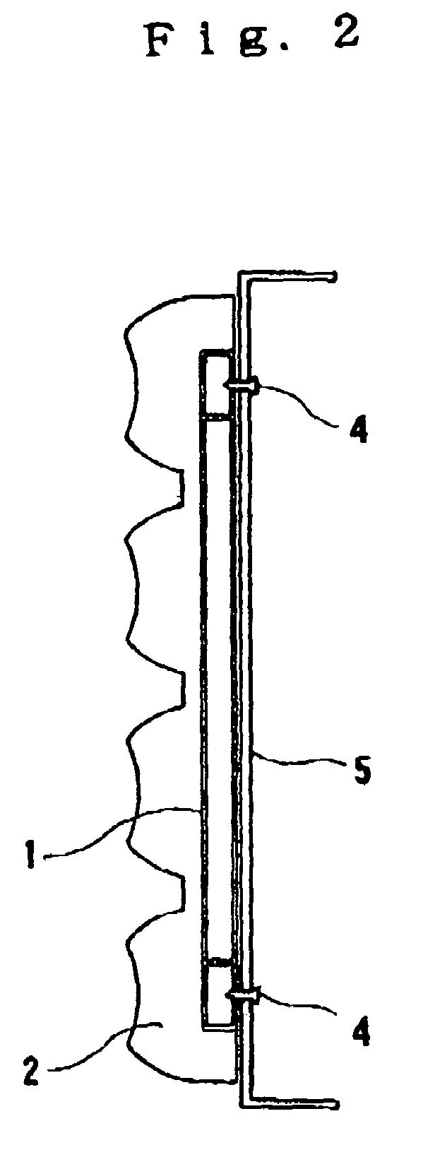
[0066]For each composition, mold-integration with a support as shown in FIGS. 1 and 2 was performed under a pressure of 12 N / cm2. Artificial stone panels having a total thickness of 23 mm and a height (depth) of 13 mm in asperity (concavo-convex portion) was molded, using a steel frame having a thickness of 6 mm as the support. As a result, as shown in Table 1, a cure shrinkage factor was controlled to less than 0.2% for compositions 1 to 5 referring to the invention of the present application, and high-quality artificial stone panels completely free of warpage and cracks were obtained. Other properties of this wall material, such as a strength, were also good.

[0067]Meanwhile, for comparative compositions 1 to 3, warpage and fine cracks were observed, and these were not suitable as a wall pa...

example 2

[0070]Composition of an artificial stone body was as follows.

[0071]

Resin component20% by weight(details)methyl methacrylate40%butyl methacrylate30%acrylic resin30%Curing agent, etc.1% by weightInorganic fine powder component58% by weight(180 μm to 5 mm)transparent natural10%(details)silica rockgranite90%Inorganic finely divided component21% by weightAluminum hydroxide(less than 180 μm, averagegrain size 70 μm)

[0072]An ambient temperature-setting mixture of the foregoing composition was charged into a bottom mold, and a support (total height: 10 mm) in combination with a steel frame (thickness: 6 mm) and an irregularly finished plate (height: 10 mm) as shown in FIGS. 3 and 4, were pressed with a top mold at a pressure of 10 N / cm2 while applying vibration. A resulting product was cured at room temperature for approximately 30 minutes.

[0073]After withdrawal from the molds, a mold-integrated artificial stone wall panel (total thickness: 23 mm) with a support embedded thereto was obtaine...

example 3

[0074]An artificial stone wall panel was molded in accordance with Example 2 using the steel fittings shown in FIGS. 5 and 6 (case 3). Here, each steel fitting (FIG. 9) is made of SS41 coated with pentite (Zn). Sizes thereof (mm) are shown in FIG. 9. A total thickness of the artificial stone wall panel was 20 mm. Height (depth) of asperity at a surface of the artificial stone was 10 mm. In this case, a withdrawal destruction load of an embedded steel fitting portion was 420 kgf / fitting.

[0075]For cases using steel fittings shown in FIGS. 10 to 12 instead of the above mentioned steel fittings, each withdrawal destruction load of each embedded steel fitting was measured as follows;[0076]steel fitting shown in FIG. 10 (SUS 304): 864 kgf[0077]steel fitting shown in FIG. 11 (SUS 304): 1052 kgf[0078]steel fitting shown in FIG. 12 (SUS 304): 733 kgf


PUM

PropertyMeasurementUnit
depthaaaaaaaaaa
transparentaaaaaaaaaa
sizeaaaaaaaaaa

Abstract

An artificial stone wall panel comprises: an artificial stone, composition of which comprises an inorganic fine powder component with a size of from 9.5 mm to 180 μm, an inorganic finely divided component with a size of less than 180 μm, and a resin component in an amount of from 7 to 30% by weight based on a total artificial stone composition, with a weight ratio of the inorganic fine powder component to the inorganic finely divided component (inorganic fine powder component:inorganic finely divided component) being in a range of from 1:1 to 5:1; and a support for installing the artificial stone onto a wall surface, embedded in the artificial stone, wherein part of the support is exposed at a back surface or edge surface of the artificial stone. This artificial stone wall panel is realized by mold-integrating an artificial stone and structure for installing such artificial stone to an external wall surface, and may be used as an external wall material with excellent design having clear contrast and natural texture.

Description

TECHNICAL FIELD[0001]The invention of this application relates to an artificial stone wall panel and a process for producing the same. More specifically, the invention of this application relates to an artificial stone wall panel which has an excellent design, enables easy installation, and is useful as a wall finishing material for architecture and construction.BACKGROUND ART[0002]External walls of large structures such as buildings have been finished by directly applying a coating or tiling to a surface of a concrete body at a construction site or, as in a curtain wall, by precast-molding or connecting a concrete body and a finishing material at a factory and fabricating at the construction site.[0003]On the other hand, for an external wall of a structure such as a house, large panels, such as siding boards subjected to premolding and precoating to form an irregular external surface, fixed on a stud or a base panel made of wood or steel, has been generally widespread.[0004]For exa...

Claims


Application Information

Patent Timeline
Patent Type & Authority Patents(United States)
IPC IPC(8): B32B3/12B32B27/20B32B5/16C04B14/02B29C39/00B29C39/10B29C70/78C04B26/06E04F13/08E04F13/14
CPCC04B26/06E04F13/08E04F13/0816E04F13/147B29C39/10C04B14/048C04B14/06C04B14/303C04B20/008C04B20/0076B29C39/003Y10T428/2991B29C70/78B29K2709/00B29L2007/002C04B2103/0046C04B2103/0047C04B2111/34C04B2111/54Y10T428/24405Y10T428/22Y10T428/2998E04F13/0819
Inventor SAKAI, MIEKOSAITO, KENICHIRO
Owner DOPPEL
Why Eureka
Try Eureka