Unmanned aerial vehicle
A drone and fuselage technology, applied in the field of unmanned aerial vehicles, can solve problems such as user loss, crash, rotor damage, etc., to reduce damage, reduce falling speed, and avoid collision accidents.
Active Publication Date: 2018-09-11
贵州大鸟创新科技有限公司
View PDF9 Cites 4 Cited by
- Summary
- Abstract
- Description
- Claims
- Application Information
AI Technical Summary
Problems solved by technology
[0003] UAVs often need to span a long space area during the operation process. During this process, they will inevitably encounter flocks of birds flying in the air. Birds are often fatal to the damage of UAVs. Once UAVs stray into In the flock of birds, the rotor is easily damaged, and then crashes, causing losses to users
Method used
View moreImage
Smart ImageViewing Examples
Examples
Embodiment Construction
[0022] The present invention will be described in further detail below by means of specific embodiments:
Login to View More PUM
 Abstract
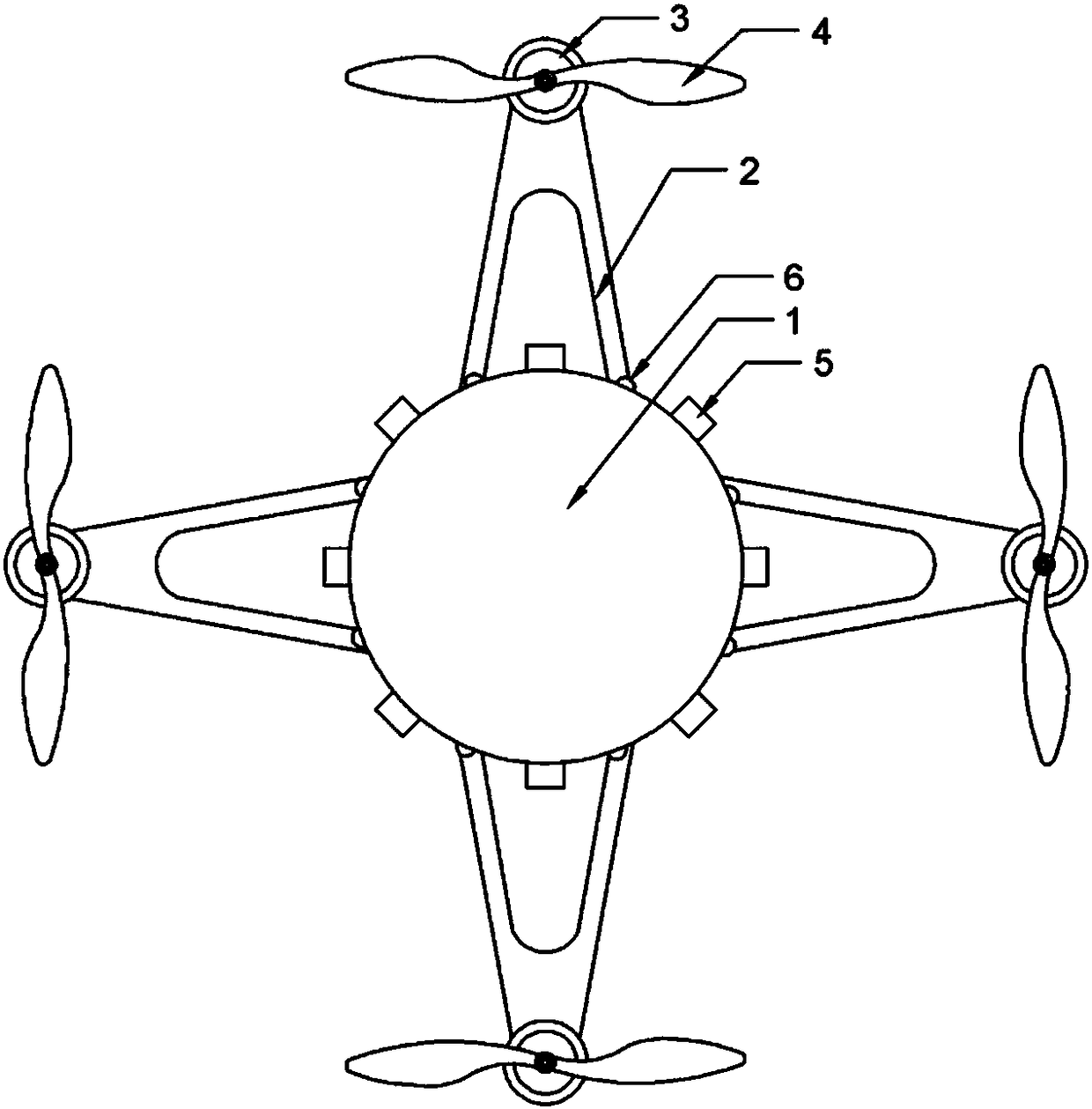
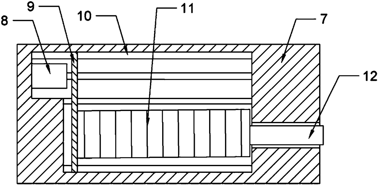
The invention relates to the technical field of unmanned flight vehicles and in particular relates to an unmanned aerial vehicle. The unmanned aerial vehicle comprises a fuselage, wherein the fuselageis provided with vehicle arms; a first motor is arranged at a free end of each vehicle arm; a rotor wing is arranged on an output shaft of each first motor; the fuselage is further provided with a control module; the control module comprises a controller and an attitude sensor; the controller is in signal connection with the motors and the attitude sensor; the controller can be used for controlling the rotation of the motors according to data of the attitude sensor; air injection devices are uniformly arranged in the peripheral direction of the fuselage; the attitude sensor comprises a gyroscope and an acceleration sensor; the controller can be used for detecting attitude data of the fuselage according to the data of the gyroscope; the controller is used for controlling the air injectiondevice to carry out air injection according to the data of the attitude sensor. The unmanned aerial vehicle provided by the invention can rapidly get away from and dispel bird flocks when meeting thebird flocks.
Description
technical field [0001] The present invention relates to the technical field of unmanned aerial vehicles, in particular to an unmanned aerial vehicle. Background technique [0002] Unmanned aircraft, referred to as "UAV", is an unmanned aircraft controlled by radio remote control equipment and its own program control device. In recent years, China's UAV industry has made great progress. UAVs can be divided into fixed-wing UAVs, rotary-wing UAVs, unmanned airships, umbrella-wing UAVs and flapping-wing UAVs according to the configuration of the flight platform. Among them, rotor UAVs, especially multi-rotor UAVs, are widely used in aerial photography, agriculture, plant protection, miniature selfies, express delivery, disaster relief, observation of wild animals, and monitoring of infectious diseases due to their strong mobility and flexibility. , surveying and mapping, news reporting, power inspection, disaster relief, film and television shooting and other fields of applicat...
Claims
Login to View More Application Information
Patent Timeline
 IPC IPC(8): B64C27/08B64C15/14B64D45/00A01M29/32
CPCA01M29/32B64C15/14B64C27/08B64D45/00B64D2045/0095B64U10/10
Inventor 王立发
Owner 贵州大鸟创新科技有限公司
Features
- R&D
- Intellectual Property
- Life Sciences
- Materials
- Tech Scout
- Unparalleled Data Quality
- Higher Quality Content
- 60% Fewer Hallucinations
Learn More Browse by: Latest US Patents, China's latest patents, Technical Efficacy Thesaurus, Application Domain, Technology Topic, Popular Technical Reports.
© 2025 PatSnap. All rights reserved.Legal|Privacy policy|Modern Slavery Act Transparency Statement|Sitemap|About US| Contact US: help@patsnap.com


