Blast furnace hearth sidewall monitoring method

A blast furnace and hearth technology, which is applied in the field of monitoring the side wall of blast furnace hearth, can solve the problems of misjudgment and missed judgment, fluctuation, and no quantitative description of the severity of side wall damage.

Inactive Publication Date: 2018-09-11
CENT SOUTH UNIV
View PDF5 Cites 14 Cited by
  • Summary
  • Abstract
  • Description
  • Claims
  • Application Information

AI Technical Summary

Problems solved by technology

However, since different types of damage and changes in cooling conditions can affect these detection data, and the actual operation of the blast furnace is often accompanied by changes in various factors, under these conditions, existing methods often make misjudgments and missed judgments, and Existi

Method used


Image

  • Blast furnace hearth sidewall monitoring method
  • Blast furnace hearth sidewall monitoring method
  • Blast furnace hearth sidewall monitoring method

Examples


Embodiment 1

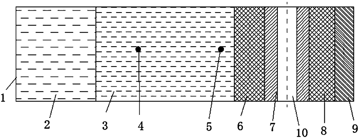
[0092] A method for monitoring the side wall of a blast furnace hearth. The side wall of the blast furnace hearth (that is, from the hot surface of the furnace wall 1 outward) includes a first brick lining 2, a second brick lining 3, and a second brick lining sequentially arranged from inside to outside. A packing layer 6, cooling stave 7, a second packing layer 8 and furnace shell 9, see figure 1 , The second brick lining 3 is provided with a first group of temperature measuring elements 4 and a second group of temperature measuring elements 5 in sequence from the inner side to the outer side of the side wall (here the first group of temperature measuring elements and the second group of temperature measuring elements are used Thermocouple), a cooling water pipe 10 is provided in the cooling wall 7. The monitoring method includes the following steps:

[0093] Obtain the angular heat flux density at the monitoring position of the side wall of the hearth, specifically obtained by...

Embodiment 2

[0166] The difference between Embodiment 2 and Embodiment 1 is:

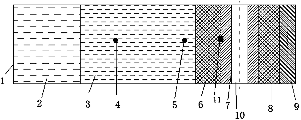
[0167] 1. A measuring element group 11 is installed on the side wall of the blast furnace hearth. The measuring element group includes a heat flow meter for measuring heat density and a third group of temperature measuring elements for measuring temperature. Here, the heat flow meter and the third group are preferred. The temperature measuring elements (optional temperature sensors) are arranged between the first packing layer 6 and the cooling stave 7 (the measuring element group here can be an integrated part of a heat flow meter and the third group of temperature measuring elements), see image 3 . In actual application, the heat flow meter can be installed at any position in the radial direction of the temperature measuring points of the two sets of thermocouples, and the third temperature measuring element is arranged between the first packing layer and the cooling water pipe.

[0168] 2. The angular heat flux ...


PUM


Abstract

The invention provides a blast furnace hearth sidewall monitoring method. According to the monitoring method, the angular heat flow densities of hearth sidewall monitoring positions are obtained, thetemperature is detected by a thermocouple arranged in carbon bricks of the hearth, based on the angular heat flow densities, the temperature, and the angular heat flow density of the hearth lining, the heat resistant values of different positions can be calculated, and the damages of the hearth sidewall can be diagnosed. According to the method, the change rules of onsite detected variables such as temperature are used to judge the situation of a blast furnace hearth; through the thermal resistant values of different positions and change rates in a certain period, the hearth can be diagnosed,the wrong judgment caused by onsite interference, fluctuation of the furnace situations, and change of cooling conditions can be eliminated, and multiple types of damages can be effectively diagnosedat the same time.

Description

Technical field [0001] The invention relates to the technical field of blast furnaces, in particular to a method for monitoring the side walls of a blast furnace hearth. Background technique [0002] The iron and steel industry is the foundation of the country's industrialization and plays a very important role in the development of the national economy. Blast furnace ironmaking is the most important production process in the modern iron and steel industry. With the increase in blast furnace size and smelting intensity, the problem of blast furnace life has become increasingly prominent. The lining of the hearth of the blast furnace is in direct contact with the hot molten iron, which is more susceptible to damage than other parts. During the operation of the blast furnace, the common forms of damage to the lining of the hearth include hot surface lining brick erosion, carbon brick ring cracking, and filler layer air gaps. These damages directly affect the life of the hearth and...

Claims


Application Information

Patent Timeline
IPC IPC(8): C21B7/24C21B7/06
CPCC21B7/06C21B7/24C21B2300/04
Inventor 宋彦坡张科高东波彭小奇周萍陈卓张建智汪攀辉李汶珊
Owner CENT SOUTH UNIV
Why Eureka
Try Eureka