Blade tip ejecting self-driven wheeled fan engine

A self-propelled, engine-based technology, applied in the direction of gas turbine devices, machines/engines, jet propulsion devices, etc., can solve the problems of multi-stage turbines with heavy weight, complex and uncompact structures, etc., and achieve mass reduction, weight reduction, and structural strength. Effect

Pending Publication Date: 2018-09-11
NANJING UNIV OF AERONAUTICS & ASTRONAUTICS
View PDF3 Cites 6 Cited by
  • Summary
  • Abstract
  • Description
  • Claims
  • Application Information

AI Technical Summary

Problems solved by technology

[0012] Purpose of the invention: In order to overcome the deficiencies in the prior art, the present invention provides a blade-tip jet self-driven wheeled fan engine, which has the following advantages: (1) solve the problem of large bypass ratio turbofan engine multi-stage turbine weight, structure complex and incomprehensible problems

Method used


Image

  • Blade tip ejecting self-driven wheeled fan engine
  • Blade tip ejecting self-driven wheeled fan engine
  • Blade tip ejecting self-driven wheeled fan engine

Examples


Embodiment Construction

[0035] The present invention will be further described below in conjunction with the accompanying drawings and embodiments.

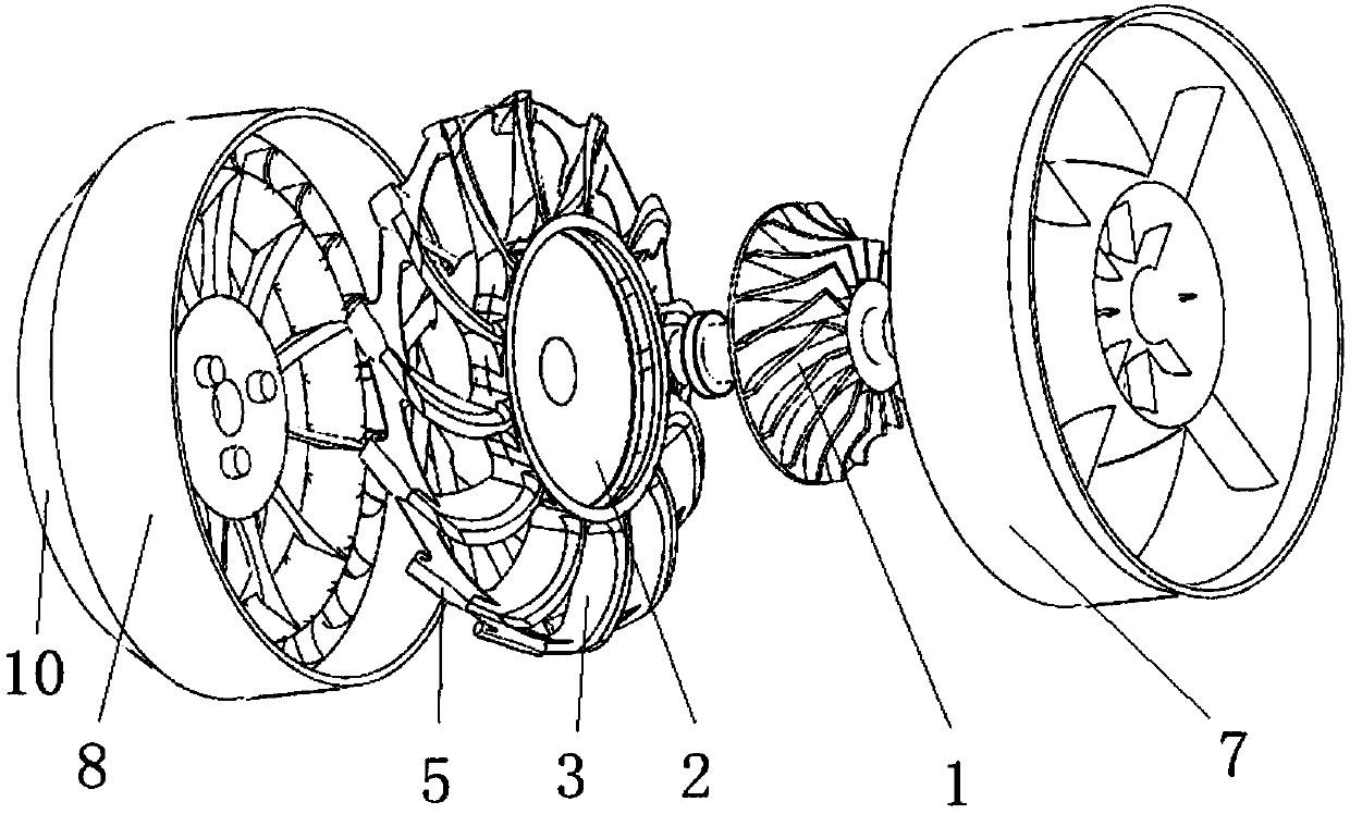
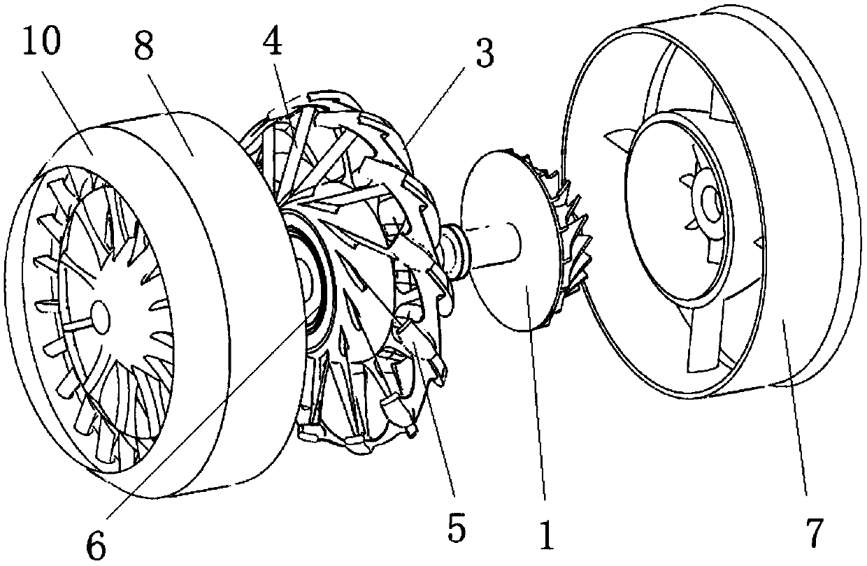
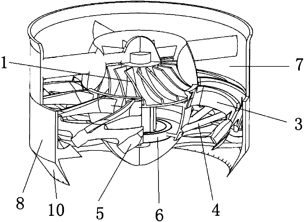
[0036] like figure 1 , 2 Shown is a blade-tip jet self-driven wheel fan engine, including a front casing 7, a rear casing 8, and two counter-rotating rotors wrapped between the front casing 7 and the rear casing 8, and the two The counter-rotating rotors are compressor rotor 1 and self-driven wheel fan 2 respectively;

[0037] like Figure 4 As shown, the compressor rotor 1 includes an integrally connected compressor shaft and impeller; Figure 5 , 6 As shown, the self-driven wheel fan 2 includes a central sleeve, 2 to 100 hollow fan blades 3, a tip combustion chamber 5, an oil supply pipe 4 and a fan hoop 9; the hollow fan blade 3 and the oil supply pipe 4 Evenly distributed on the outside of the center sleeve along the circumference, the hollow fan blades 3 are connected to the front end of the outer wall of the center sleeve, the oil supply pipe...


PUM


Abstract

The invention discloses a blade tip ejecting self-driven wheeled fan engine. The blade tip ejecting self-driven wheeled fan engine comprises a hollow fan with a combustion chamber being arranged at ablade tip. High-pressure gas is provided by a central gas compressor, flows to the blade tip combustion chamber along hollow blades to be combusted and then is ejected out to the lateral rear portion,and the fan is driven by reactive force of jet flow to rotate; and the rotating fan drives the central gas compressor through a planet gear device in a rear casing, and thus circulation operation ofthe whole engine is established. Through the bicycle-wheel-like design that the fan blades, an oil supply pipe and a circumferential band of an outer ring of the fan are combined together, the good stiffness and strength can be maintained under high speed rotation. Compared with existing high-bypass-ratio turbofan engines, a turbine part is omitted, and the structure is lighter and more compact; compared with existing propeller tip ejecting rotor wings of helicopters, the thermal efficiency of the engine is higher; and meanwhile, due to the fact that the turbine is omitted, thermal limiting ofturbine materials is avoided, and the temperature of the combustion chamber of the engine can be further increased compared with that of existing engines.

Description

technical field [0001] The invention relates to a blade-tip jet self-driven wheeled fan engine, which belongs to the technical field of aeroengines, and is suitable for aircrafts pursuing high thrust-to-weight ratio or high efficiency at subsonic speeds, especially for civil airliners, military transport aircraft, high-altitude long-endurance without It has good application prospects for man-machines, and even for some vertical or short take-off and landing aircraft in the future. Background technique [0002] The blade-tip combustion chamber jet drive technology was first applied to the helicopter rotor. In the 1950s, the Miri Design Bureau of the former Soviet Union began the research on the blade-tip jet rotor helicopter. It developed a small four-seater blade-tip jet helicopter B -7, this helicopter places the turbojet engine at the tip of the rotor, and drives the rotor to rotate along the circumferential jet. [0003] In 1984, Canada designed a helicopter in which the...

Claims


Application Information

Patent Timeline
Patent Type & Authority Applications(China)
IPC IPC(8): F02K3/072F02C3/16
CPCF02C3/165F02K3/072
Inventor 李传鹏刘然李传意孙子桓
Owner NANJING UNIV OF AERONAUTICS & ASTRONAUTICS
Why Eureka
Try Eureka