Buffering oil cylinder

A buffer oil cylinder and buffer cylinder technology, applied in the field of hydraulic oil cylinders, can solve the problems of easy stuck valve core, insufficient reliability, and inability to reliably realize high-speed and heavy-load use occasions, and achieve good safety, reliability, and flexible structure. Effect

Pending Publication Date: 2018-09-11
中山市智泰机电科技有限公司
View PDF16 Cites 10 Cited by
  • Summary
  • Abstract
  • Description
  • Claims
  • Application Information

AI Technical Summary

Problems solved by technology

This buffering method has various structural forms, which can meet the smooth braking of the oil cylinder in low-speed and light-load applications, and has the advantages of compact structure and high reliability; but no matter what kind of structure it adopts, this buffering method has the following disadvantages: A problem: ①Limited by the structure and installation size of the oil cylinder, its buffer capacity is small, which cannot meet the requirements of smooth braking of the oil cylinder in high-speed and heavy-duty applications; ②Since the buffer device is arranged inside the oil cylinder, the adjustment and maintenance of the buffer device are difficult. Difficult; ③Because part of the buffer device is integrated with or connected to the moving parts of the cylinder, the machining accuracy requirements are high, especially for oil cylinders with long buffer strokes, the processing accuracy is even stricter; ④Since the buffer device may be in the The instantaneous high pressure inside the cylinder has a certain impact on the safety of the hydrau

Method used


Image

  • Buffering oil cylinder
  • Buffering oil cylinder
  • Buffering oil cylinder

Examples


Embodiment Construction

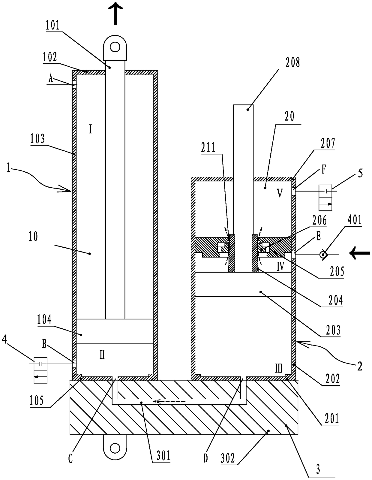
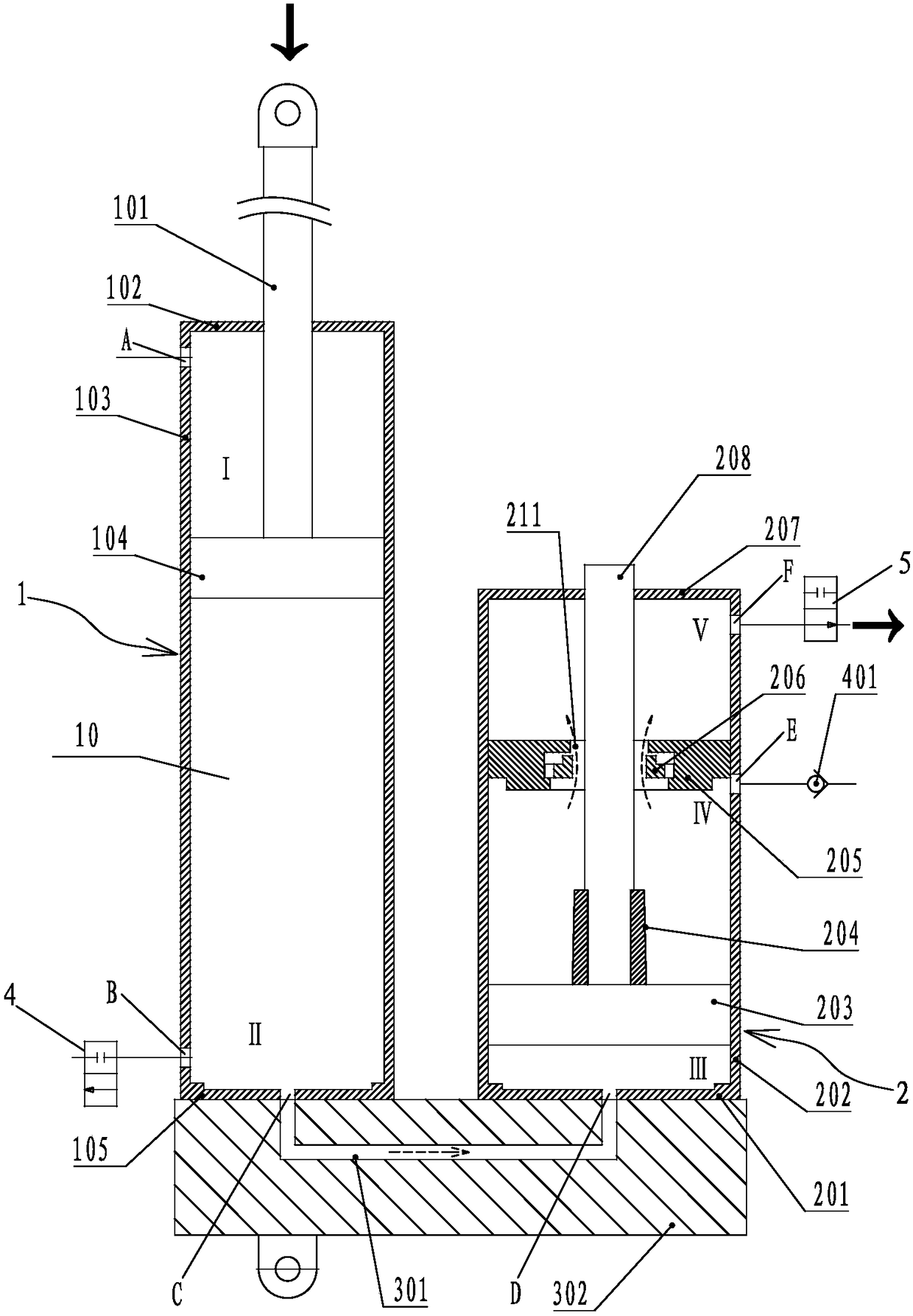
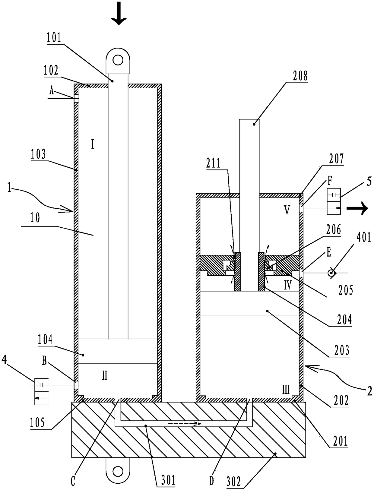
[0033] The present invention will be further described below in conjunction with accompanying drawing:

[0034] The front (front end) referred to in the present invention refers to an end that the piston rod protrudes, and the rear (rear end) is an end opposite to the front (front end).

[0035] Such as Figure 1 to Figure 4 The shown buffer cylinder is an embodiment of one-way buffering in the present invention, including a power cylinder 1 and a buffer converter 2, the buffer converter 2 is independently arranged outside the power cylinder 1, and the power cylinder 1 includes The power cylinder block 10 made up of the front end cover 102, the power cylinder 103 and the rear end cover 105 is arranged at the center of the power cylinder 103 and passes through the power piston rod 101 of the front end cover 102 and is connected with the power piston rod 101 and connected with the power cylinder 101. The power piston 104 matched with the inner cavity of the cylinder 103, the in...


PUM


Abstract

The invention discloses a buffering oil cylinder. The buffering oil cylinder comprises a power cylinder used for connection with a load, wherein a buffering convertor is independently arranged on theexterior of the power cylinder; a power module and a buffering function module of the buffering oil cylinder are separately arranged and are connected through a channel connector; an oil line system is used for supplying oil to a buffering cavity and an oil return cavity and converting high pressure hydraulic oil from a hydraulic system into high pressure oil of a working cavity of the power cylinder, so that the power cylinder generates push force or pull force; when the power cylinder works reversely, the hydraulic oil of the working cavity of the power cylinder flows into a converting cavity of the buffering convertor so as to push a piston rod and a piston of the buffering convertor to move forwards; and when a buffering body on the piston rod enters a cushioning stroke, the flow areaof a buffering channel decreases to form a throttling channel, the pressure of the buffering cavity rapidly rises, and the pressure of the working cavity of the power cylinder also quickly rises to form resistance acting on the piston and piston rod of the power cylinder, so that a moving part of the power cylinder and a driven object gradually decelerate till stopping.

Description

【Technical field】 [0001] The invention belongs to the technical field of hydraulic oil cylinders, in particular to a buffer oil cylinder with high reliability and suitable for high-speed and heavy-load applications. 【Background technique】 [0002] The biggest advantage of hydraulic transmission is that its power-mass ratio and force-mass ratio are large, especially when it is medium and high-power and realizes linear reciprocating motion. The hydraulic cylinder is the actuator for hydraulic transmission to achieve linear reciprocating motion. When the hydraulic cylinder When the moving part and the moving object with a certain mass reciprocate quickly, there will be a lot of kinetic energy at the end of the stroke. If there is no buffer device at the end of the stroke, the moving part will brake smoothly. The inertial force and hydraulic pressure of the moving part will cause the piston to The mechanical impact with the end cover will produce impact, noise, and even damage t...

Claims


Application Information

Patent Timeline
IPC IPC(8): F15B15/22
CPCF15B15/228F15B2215/30
Inventor 赖书红
Owner 中山市智泰机电科技有限公司
Why Eureka
Try Eureka