
Conveying mechanism used for machining and capable of conveniently adjusting feeding speed

A technology of mechanical processing and conveying mechanism, which is applied in the direction of metal processing, etc., can solve the problems of reducing the efficiency and adaptability of processing machinery feeding, the inability to adjust the stroke of conveying materials, and the inability to adjust the conveying speed and mode, etc., so as to improve adaptability and Efficiency, efficiency improvement, and stability improvement effect

Active Publication Date: 2021-03-02
佛山伟祥自动化有限公司
View PDF11 Cites 0 Cited by
  • Summary
  • Abstract
  • Description
  • Claims
  • Application Information

AI Technical Summary

Problems solved by technology

[0003] However, the existing mechanical processing conveying mechanism cannot quickly and stably adjust the conveying speed and mode according to the demand when conveying raw materials to the processing machinery, and at the same time, it cannot specifically adjust the feeding stroke according to the size of the processing machinery, which reduces the need for subsequent processing. The efficiency of mechanical feeding and the overall adaptability of the device, so there is an urgent need for a conveying mechanism for mechanical processing that is easy to adjust the feeding speed to solve the above-mentioned problems

Method used


Image

  • Conveying mechanism used for machining and capable of conveniently adjusting feeding speed
  • Conveying mechanism used for machining and capable of conveniently adjusting feeding speed
  • Conveying mechanism used for machining and capable of conveniently adjusting feeding speed

Examples


Embodiment Construction

[0030] The following will clearly and completely describe the technical solutions in the embodiments of the present invention with reference to the accompanying drawings in the embodiments of the present invention. Obviously, the described embodiments are only some, not all, embodiments of the present invention. Based on the embodiments of the present invention, all other embodiments obtained by persons of ordinary skill in the art without making creative efforts belong to the protection scope of the present invention.

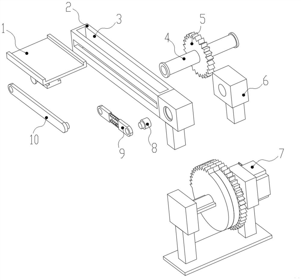
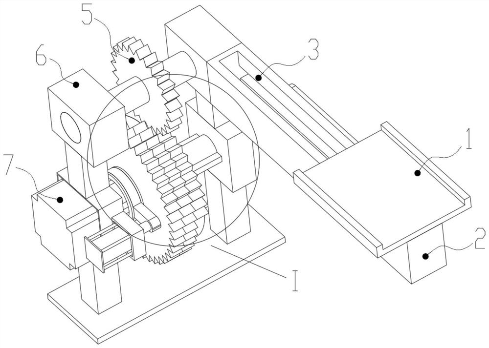
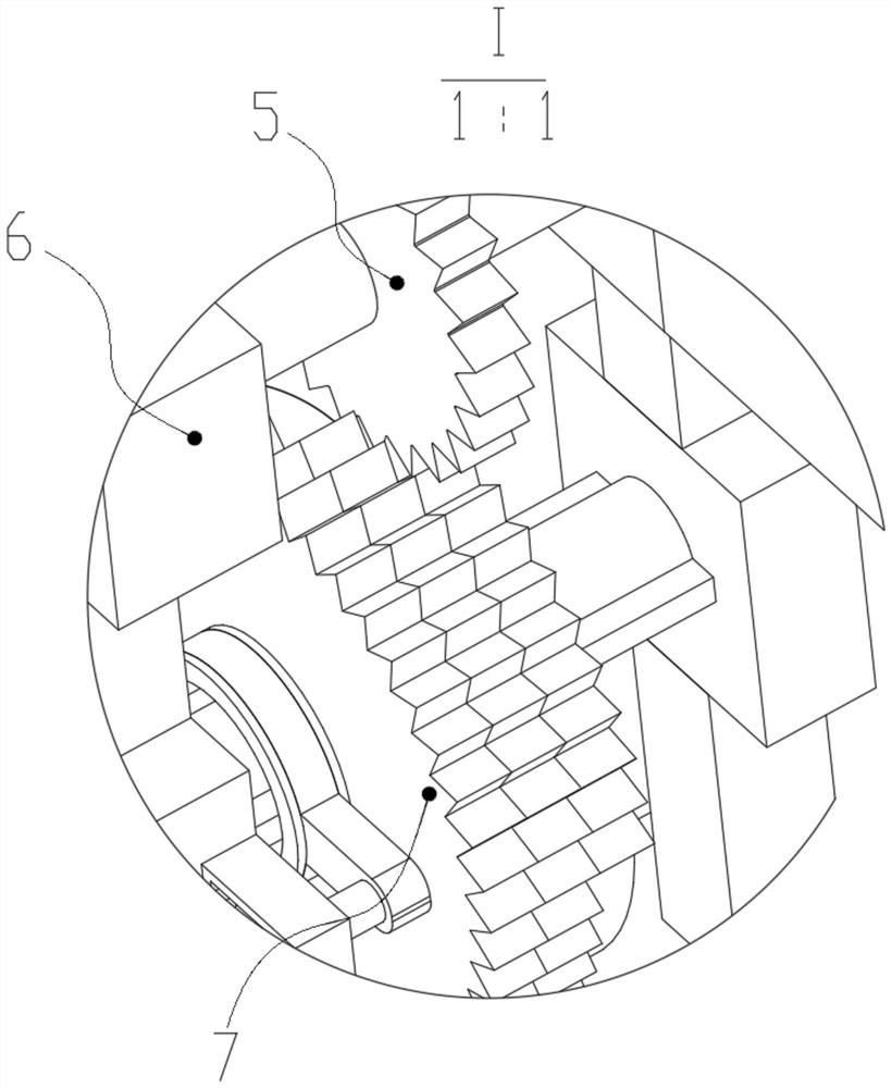
[0031] see Figure 1-6 , an embodiment provided by the present invention: a conveying mechanism for mechanical processing that is convenient for adjusting the feeding speed, including a conveying plate 1, a positioning guide rail 2, a limit chute 3, a limit card shaft 4, a transmission gear 5, an installation Support 6, adjustment mechanism 7, positioning shaft 8, support mechanism 9 and turnover plate 10,

[0032]The upper end surface of the adjustment mecha...


PUM


Abstract

The invention discloses a conveying mechanism used for machining and capable of conveniently adjusting the feeding speed. The conveying mechanism comprises a conveying plate, a positioning guide rail,a limiting sliding groove, a limiting clamping shaft, a transmission gear, mounting supports, an adjusting mechanism, a positioning shaft, a supporting mechanism and an overturning plate, wherein theupper end face of the adjusting mechanism is symmetrically and fixedly connected with the mounting supports used for limiting. According to the conveying mechanism, by arranging the supporting mechanism, if the conveying stroke of the conveying plate needs to be adjusted, a user can clamp the conveying stroke into a hexagonal clamping plate at the bottom of a threaded sleeve through an external tool, then the hexagonal clamping plate is rotated, and the threaded sleeve and a threaded shaft rotate relatively, so that the subsequent rapid adjustment of the distance between the threaded sleeve and the threaded shaft is facilitated, and the adaptability of the device is improved; and meanwhile, limiting springs and second adjusting rods can provide enough buffering capacity during movement, so that the transmission stability is improved, the distance between the threaded shaft and the threaded sleeve can be limited, and the supporting stability after adjustment is improved.

Description

technical field [0001] The invention relates to the technical field of mechanical equipment, in particular to a conveying mechanism for mechanical processing which is convenient for adjusting the feeding speed. Background technique [0002] When machining the workpiece, the processing machinery can change the shape, size, position and properties of the workpiece through casting, forging, stamping, welding, machining, assembly and other processes, so that the workpiece becomes a finished or semi-finished product, which is convenient for subsequent processing. The workpiece is being processed or transported, and the conveying mechanism can provide sufficient raw materials for the processing machinery during processing, thereby improving the efficiency of subsequent processing. [0003] However, the existing mechanical processing conveying mechanism cannot quickly and stably adjust the conveying speed and mode according to the demand when conveying raw materials to the processi...

Claims


Application Information

Patent Timeline
Patent Type & Authority Applications(China)
IPC IPC(8): B23Q7/00
CPCB23Q7/00
Inventor 俞林锋
Owner 佛山伟祥自动化有限公司
Learn More