Double-voltage driving circuit of high-speed switch valve

A high-speed on-off valve and drive circuit technology, applied in the valve operation/release device, valve details, valve device and other directions, can solve the problem of unable to meet the fast opening and release requirements of high-speed on-off valve, etc., to improve the service life and circuit structure. Simple, low-cost effects

Pending Publication Date: 2018-09-11
QINZHOU UNIV
View PDF4 Cites 4 Cited by
  • Summary
  • Abstract
  • Description
  • Claims
  • Application Information

AI Technical Summary

Problems solved by technology

[0005] The present invention aims at the problem that the existing single-voltage driven high-speed switch valve drive circuit cannot meet the requirements of fast opening and release of the high-speed switch valve, and provides a dual-voltage drive circuit for the high-speed switch valve

Method used


Image

  • Double-voltage driving circuit of high-speed switch valve

Examples


Embodiment Construction

[0011] In order to make the object, technical solution and advantages of the present invention clearer, the present invention will be further described in detail below in combination with specific examples and with reference to the accompanying drawings.

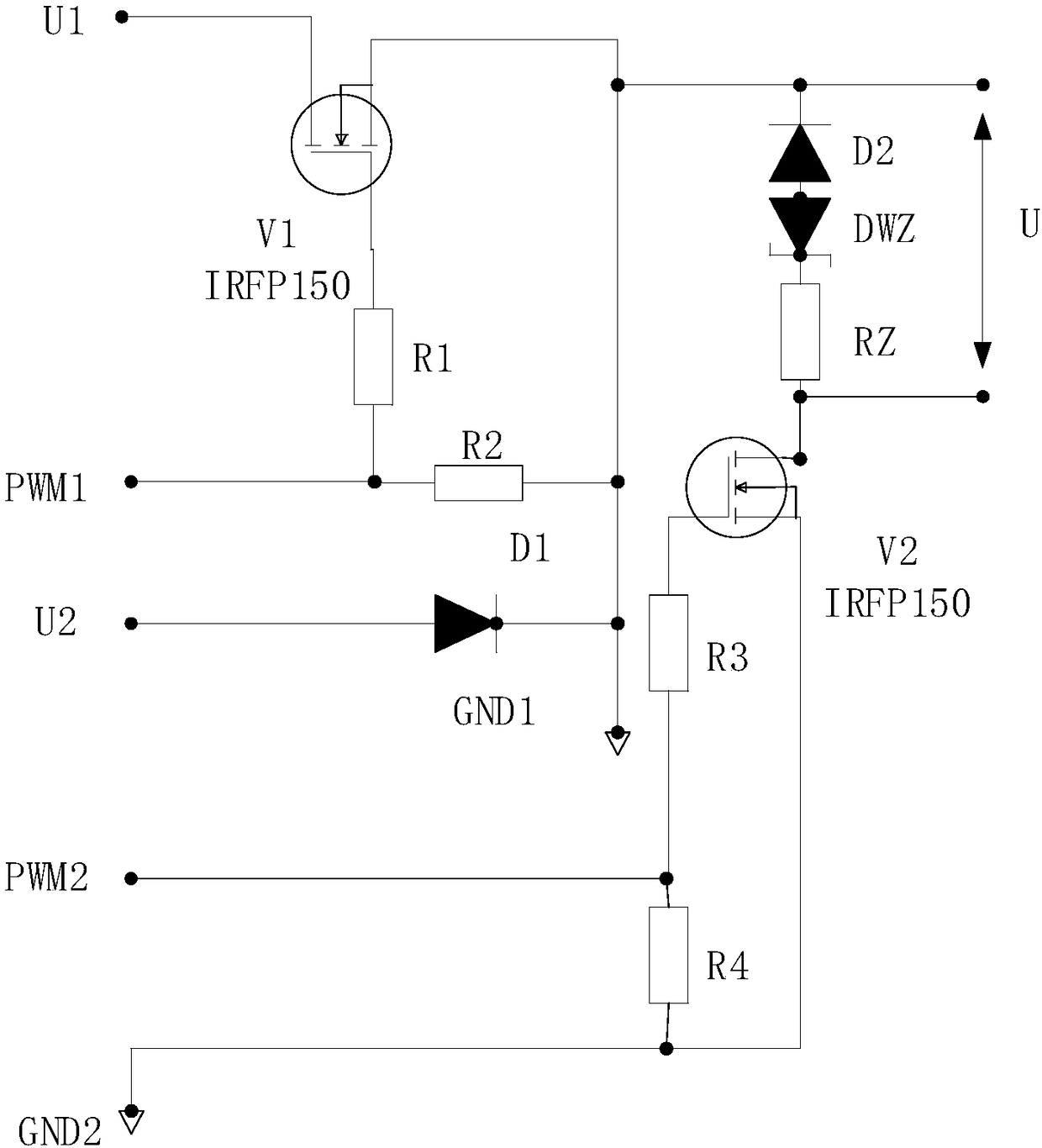
[0012] see figure 1 , a dual-voltage drive circuit for a high-speed switching valve, consisting of a high-voltage voltage source U1, a low-voltage voltage source U2, a high-voltage control switch V1, a drive control switch V2, diodes D1 and D2, a voltage regulator tube DWZ, and a resistor RZ. The high-voltage control signal PWM1 is connected to the control terminal of the high-voltage control switch V1; the output terminal of the high-voltage voltage source U1 is connected to one terminal of the high-voltage control switch V1; the output terminal of the low-voltage voltage source U2 is connected to the input terminal of the diode D1, and the output terminal of the diode D1 Connect the other end of the high-voltage control sw...


PUM


Abstract

The invention discloses a double-voltage driving circuit of a high-speed switch valve. The double-voltage driving circuit is characterized in that a high-voltage control signal PWM1 is connected to the control end of a high-voltage control switch V1, the output end of a high-voltage voltage source U1 is connected with one end of the high-voltage control switch V1, the output end of a low-voltage voltage source U2 is connected with the other end of the high-voltage control switch V1 and the cathode end of a diode D2 through a diode D1, a driving control signal PWM2 is connected to the control end of a driving control switch V2, one end of the driving control switch V2 is grounded, the other end of the driving control switch V2 is connected with one end of a resistor RZ, the other end of theresistor RZ is connected with the cathode of a voltage-regulator tube DWZ, and the anode of the voltage-regulator tube DWZ is connected with the anode of the diode D2. According to the double-voltagedriving circuit of the high-speed switch valve, the structure is simple, the cost is low, the valve element pull-in and drop-out retardation time can be effectively shorten, and furthermore, a high-voltage power supply and a low-voltage power supply are used in a altering mode, so that heating of a coil is greatly reduced, and the service life of the high-speed switch valve is prolonged.

Description

technical field [0001] The invention relates to the technical field of high-speed switching valves, in particular to a dual-voltage drive circuit for high-speed switching valves. Background technique [0002] The high-speed on-off valve is a key component of the turbocharger system of gasoline passenger cars. Since the electromagnet of the high-speed on-off valve is subjected to electromagnetic attraction and the valve core is under the action of the spring force, the response process of the high-speed on-off valve will always lag behind the PWM signal. On, off. Increasing the driving voltage in the drive circuit of the high-speed switching valve can quickly realize the pull-in response of the high-speed switching valve. However, the increase in voltage will increase the temperature rise of the coil, which will reduce the service life of the valve core. [0003] At this stage, the high-speed switch valve drive circuit developed in my country mainly adopts single-voltage dri...

Claims


Application Information

Patent Timeline
IPC IPC(8): F16K31/06H02M1/00
CPCH02M1/00F16K31/0675
Inventor 李派霞
Owner QINZHOU UNIV
Why Eureka
Try Eureka