Steam generator and steam oven

A technology of steam generator and steam furnace, which is applied in the direction of steam generation, steam generation method, steam boiler, etc. It can solve the problems of slow steam speed and long cooking cycle, reduce the possibility of fouling and high heat exchange efficiency Effect

Pending Publication Date: 2018-09-11
HANGZHOU ROBAM APPLIANCES CO LTD
View PDF11 Cites 7 Cited by
  • Summary
  • Abstract
  • Description
  • Claims
  • Application Information

AI Technical Summary

Problems solved by technology

[0003] In the existing steam ovens, the steam generators are mostly pipeline steam generators or open water pan steam generators. Although these two steam generators are widely used, they still have shortcomings and need to be improved.
For example, there is a problem with both the pipe steam generator and the open water pan steam generator, that is, the steam generation speed is relatively slow, resulting in a longer cooking cycle

Method used


Image

  • Steam generator and steam oven
  • Steam generator and steam oven
  • Steam generator and steam oven

Examples


Embodiment 1

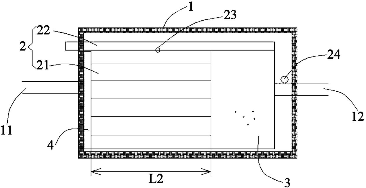
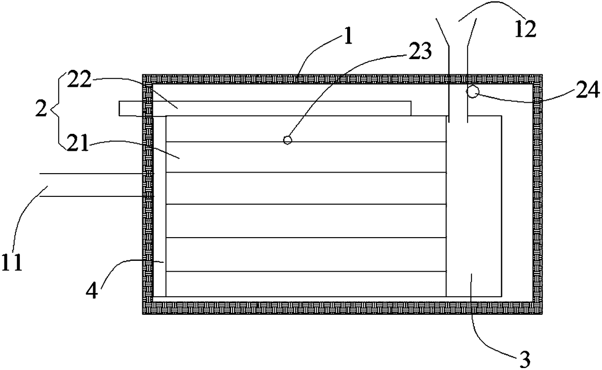
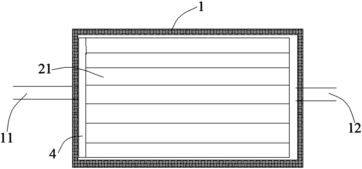
[0037] like figure 1 - image 3 As shown, the steam generator 100 provided in this embodiment includes a casing 1 provided with a water inlet 11 and an exhaust port 12, and a steam generating unit 2 disposed in the casing 1. The steam generating unit 2 includes a plurality of The gasification chamber of the channel 21 and the heating body 22 for heating the gasification chamber, the heating body 22 is in thermal contact with the gasification chamber; after the liquid enters the shell 1 through the water inlet 11, it is divided by the microchannels 21 and can be Under the action of the heating body 22 , the gas is rapidly vaporized in each microchannel 21 . The exhaust port 12 is used to discharge the steam generated in the steam generating unit 2 .

[0038] On the one hand, the steam generator 100 provided in this embodiment adopts the flow splitting technology to divide the water flow into several small water flows through a plurality of microchannels 21 . Since the inner d...

Embodiment 2

[0073] like Image 6 and Figure 7 As shown, the steam furnace provided in this embodiment includes a water tank 300, the steam generator 100 provided in the first embodiment, and a water pump 200 for transporting the water in the water tank 300 to the steam generator 100. The control between the water pump 200 and the steam furnace The system is connected, and the exhaust port 12 of the steam generator communicates with the cooking cavity of the steam oven.

[0074] The steam furnace provided in this embodiment includes the above-mentioned steam generator 100, and can achieve the beneficial effects that the above-mentioned steam generator 100 can achieve.

[0075] Specifically, the water pump 200 may be an AC water pump 200, and the AC water pump 200 is connected to the water tank 300 and the gasification chamber through a pipeline system.

[0076]The water is pumped from the water tank 300 to the gasification chamber by the AC water pump 200, and the heating body 22 and th...


PUM


Abstract

The invention provides a steam generator and a steam oven, and relates to the technical field of kitchen electric appliances. The steam generator comprises a shell body and a steam generation unit, wherein the shell body is provided with a water inlet and an exhaust port, the steam generation unit is arranged in the shell body and comprises a gasification chamber provided with a plurality of micro-channels and a heating bod used for heating the gasification chamber, and the heating body is in thermal contact with the gasification chamber; after the liquid enters the shell body from the water inlet, the liquid is divided by the micro-channels, and can be rapidly gasified in each micro-channel under the action of the heating body; and the exhaust port is used for discharging steam generatedin the steam generation unit. The steam oven comprises a water tank, the steam generator and a water pump used for conveying water in the water tank to the steam generator, wherein the water pump is connected with a control system of the steam oven, and the exhaust port of the steam generator communicates with a cooking cavity of the steam oven. According to the steam generator and the steam oven,the problem that the steam generating speed of a steam generator in an existing steam oven is low is solved.

Description

technical field [0001] The invention relates to the technical field of kitchen appliances, in particular to a steam generator and a steam oven. Background technique [0002] A steam oven is a commonly used kitchen appliance in the prior art, which brings great convenience to people's cooking and greatly improves people's cooking experience. [0003] In the existing steam furnaces, the steam generators are mostly pipeline steam generators or open water pan steam generators. Although these two steam generators are widely used, they still have shortcomings and need to be improved. For example, both in-line steam generators and open-water pan steam generators have a problem, that is, the speed of steam generation is relatively slow, resulting in a relatively long cooking cycle. [0004] Therefore, it is very necessary to design a new steam generator to improve the above technical problems. SUMMARY OF THE INVENTION [0005] The first object of the present invention is to prov...

Claims


Application Information

Patent Timeline
Patent Type & Authority Applications(China)
IPC IPC(8): F22B1/28F22B37/12A47J27/04A47J27/16
CPCA47J27/04A47J27/16F22B1/28F22B37/125
Inventor 任富佳魏华锋班永王强
Owner HANGZHOU ROBAM APPLIANCES CO LTD
Why Eureka
Try Eureka