

Energy storage buried pipe heat exchange system
A technology of heat exchange system and buried pipe, which is applied in the field of buried pipe heat exchange system
- Summary
- Abstract
- Description
- Claims
- Application Information
AI Technical Summary
Problems solved by technology
Method used
Image

Examples
Embodiment 1
[0075] This embodiment mainly introduces the specific structure, operation mode and characteristics of the present invention.
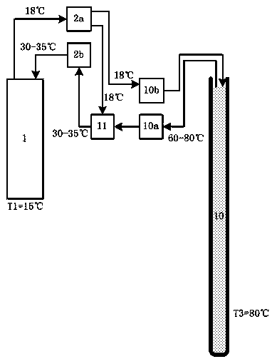
[0076] Such as image 3 As shown, it is a typical refrigeration working condition of the present invention, wherein the application system 4 is a heat pump system:
[0077] Summer: The initial value of the underground rock and soil temperature is T1=18°C; at this time, the temperature of the heat exchange medium 5 in the energy storage buried pipe 1a is usually slightly higher than the temperature of the surrounding underground rock and soil;
[0078] The heat exchange medium 5 in the energy storage underground pipe 1a is quickly extracted through the quick extraction device 2a, and the extraction temperature is about 21°C; the extracted heat exchange medium 5 is transported to the heat exchange subsystem 3 through pipelines for heat exchange The other side of the heat exchange subsystem 3 is connected to the application system 4 (heat pump system), ...
Embodiment 2
[0104] In the prior art, the insufficient area suitable for buried pipes in the construction area is a big problem. Therefore, a scheme of using building pile foundations to implement pile foundation buried pipes, that is, the energy pile system, has emerged. Energy piles refer to the pile foundations that bury closed heat exchange pipes in the foundation piles (or underground diaphragm walls) of buildings to exchange heat with rock and soil, and undertake the dual functions of structure and heat transfer at the same time (see reference 1 for details) .
[0105] Similar to the existing energy pile system, using the pile foundation to realize the energy storage buried pipe of the present invention is a solution that kills two birds with one stone, and is also an important way to implement the present invention. Therefore, in this embodiment, the prestressed pipe pile is used as the energy storage underground pipe 1a, so that the prestressed pipe pile has dual functions of build...
Embodiment 3
[0125] This embodiment is a combination of the energy storage buried pipe heat exchange system and the valley electricity energy storage to form the valley electricity energy storage composite system:
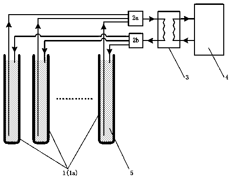
[0126] The system includes an energy storage buried pipe array 1, a rapid replacement subsystem 2, a heat exchange subsystem 3, and a valley electricity cooling / heating system 8; the valley electricity refrigeration / heating system 8 is an air-cooled heat pump unit, Water-cooled heat pump unit or electric heating unit.
[0127] The off-peak power cooling / heating system 8 operates during the off-peak power period to supply energy to the energy storage buried pipe array 1 and the underground rock and soil mass. When the off-peak power refrigeration / heating system 8 is running, the energy storage buried pipe array 1 passes The rapid replacement subsystem 2 and the heat exchange subsystem 3 are connected to the off-peak electricity cooling / heating system 8, and the off-peak electric...
PUM
 Abstract
Description
Claims
Application Information