

Solar energy-water source heat pump combined heat-supply system
A water-source heat pump and heating system technology, applied in solar heating systems, solar thermal storage, solar thermal energy and other directions, can solve the problems of unsustainable heating, low utilization rate of stored energy of phase change heat storage devices, etc. Effective heat extraction time and the effect of improving heat exchange efficiency
- Summary
- Abstract
- Description
- Claims
- Application Information
AI Technical Summary
Problems solved by technology
Method used
Image

Examples
Embodiment 1
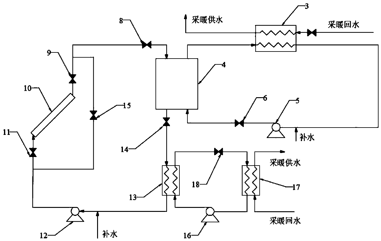
[0041] The solar heat collector 10 is used as the heat source of the system alone. This working condition is suitable for sufficient sunlight during the day, and the solar heat collector 10 heats the circulating water in the heating circulation pipeline. The six valves 11 and the seventh valve 14 are in the open state, and the eighth valve 15 is in the closed state. The heated circulating water in the phase change heat storage device 4 transfers most of the heat to the phase change material through the heat exchange coil, and It is stored in the phase change material in the form of a large amount of latent heat and a small amount of sensible heat. The circulating water after heat exchange and cooling enters from the frozen water inlet of the evaporator 13 and acts as a low-temperature heat source for the water source heat pump system. Under the action of the secondary circulation pump 12, it is transported to the solar heat collector 10 for heating, thereby completing a heating...
Embodiment 2
[0043] When the external heating demand is small, the water source heat pump system is firstly used for heating, and the heating return water is heated to the target temperature in the condenser 17 and then sent to the user side.
[0044] When the external heating demand is large, the water source heat pump alone cannot be used for heating. At this time, the phase change device 4 needs to be activated for auxiliary heating. Open the second valve 6 and start the first circulation pump 5. At this time, the phase change heat storage device 4 is in the heat release state, and the phase change material transfers the stored heat to the circulating water, and the heated fluid is heated in the heat exchanger 3 The heating returns water to complete the heating.
Embodiment 3
[0046] When the phase change heat storage device 4 is in the heat storage state at night and the outside world needs heating, close the fifth valve 9 and the sixth valve 11, open the eighth valve 15, start the second circulation pump 12, and the low-temperature circulating water is sent to the phase change Heat is taken from the heat storage device 4, and the heated circulating water is used as the heat source of the water source heat pump, and the heating demand is fulfilled by the heat pump system.
[0047] The invention uses a phase change heat storage device to replace the heat storage tank, saves the area occupied by the system, and prolongs the effective heat acquisition time of the system. Coupling solar energy, water source heat pump and phase change heat storage device, using solar collectors to store heat in the phase change heat storage device during the day; Hot, hot water is provided to the outside world. When the phase change heat storage device is in the heat s...
PUM
 Abstract
Description
Claims
Application Information