Energy-saving type hot blast stove

A hot blast stove, energy-saving technology, applied in air heaters, fluid heaters, lighting and heating equipment, etc., can solve the problems of non-compliance with energy saving and environmental protection, high flue gas discharge temperature, high heat loss from flue gas, and achieve extended use. Life, increase the heat exchange temperature difference, reduce the effect of the heat exchange area

Inactive Publication Date: 2015-06-24
JIANGNAN BOILERS & PRESSURE VESSELS ZHANGJIAGANG
View PDF7 Cites 9 Cited by
  • Summary
  • Abstract
  • Description
  • Claims
  • Application Information

AI Technical Summary

Problems solved by technology

The heat transfer coefficient of the cold side medium (air) is relatively low, the cooling condition of the heating surface is not good, and the material requirements are high; at the same time, high-temperature corrosion and high-temperature oxidation occur, causing the heating surface to burn through
[0004]2) The heat transfer coefficient of the medium on both sides of the hot blast stove is low, resulting in an increase in the heat transfer area and a decrease in compactness, resulting in higher costs
[0005]3) Most of the similar domestic products adopt bow-shaped deflector structure, and the cooling medium is easy to form a dead zone, resulting in local over-temperature damage
[0006]4) Insufficient consideration of thermal expansion, resulting in weld cracking during the expansion of the heating surface
[0007]5), the flue gas discharge temperature is high (above 300°C), and the heat loss of exhaust gas is high, which does not meet the requirements of energy conservation and environmental protection

Method used


Image

  • Energy-saving type hot blast stove

Examples


Embodiment Construction

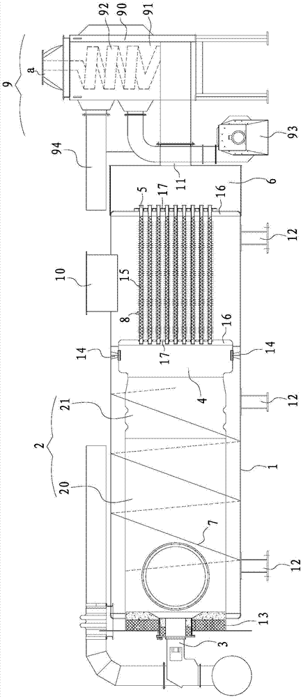
[0022] Such as figure 1 As shown, the energy-saving hot blast stove provided in this example includes a furnace body 1 extending along the horizontal direction, a combustion chamber 2 arranged in the furnace body 1, a burner 3 communicating with one end of the combustion chamber 2, and a The front smoke chamber 4 connected to the other end of the combustion chamber 2, the rear smoke chamber 6 connected to the front smoke chamber 4 through a plurality of heat exchange tubes 5, and the guide tube spirally wound on the outer periphery of the combustion chamber 2 along the length direction of the combustion chamber 2. flow plate 7 ; heat exchange fins 8 on the outer periphery of each heat exchange tube 5 ; and a combustion air preheating device 9 .

[0023] Specifically, the furnace body 1 has an air inlet 10, an exhaust port 11, and a smoke exhaust port 12. The air inlet 10 faces the heat exchange tube 5, and the smoke exhaust port 12 is arranged at the tail of the rear smok...


PUM


Abstract

The invention discloses an energy-saving type hot blast stove comprising a stove body, a burning chamber, a burner communicated with one end of the burning chamber, a front smoke chamber communicated with the other end of the burning chamber and a rear smoke chamber communicated with the front smoke chamber through multiple heat exchange pipes. The stove body is provided with an intake port, an exhaust port and a smoke vent. The intake port is opposite to the heat exchange pipes. The smoke vent is formed in the tail portion of the rear smoke chamber. The hot blast stove further comprises a deflector, heat exchange fins and a combustion air preheating device, wherein the deflector is spirally wound around the outer circumference of the burning chamber in the length direction of the burning chamber, the heat exchange fins are arranged on the peripheries of all the heat exchange pipes, and the combustion air preheating device is communicated with the smoke vent, absorbs waste heat of discharged smoke and preheats gas fed into the burner. According to the energy-saving type hot blast stove, because gas to be heated and smoke flow are arranged in a pure countercurrent mode, the heat exchange temperature difference is increased, and the heat exchange area is reduced; due to the deflector, a flushing dead corner is avoided, and the service life is prolonged; due to the combustion air preheating device, the hot blast stove saves energy and is environmentally friendly.

Description

technical field [0001] The invention relates to an energy-saving hot blast stove, in particular to a fuel oil (gas) hot blast stove used for heating air in an airflow drying device. Background technique [0002] Hot blast stoves are widely used in air heating of airflow drying devices. However, hot blast stoves are different from general heat exchangers. General heat exchangers only involve heat exchange between hot and cold fluids, and do not involve fuel combustion and corresponding The conversion from the chemical energy of the fuel to heat energy, and the hot stove must include two processes: the combustion of the fuel and the heat exchange between the combustion product and the air. In the process of realizing the two processes of the hot blast stove, there are generally problems in the following aspects: [0003] 1) Heat exchange between high-temperature flue gas generated by combustion and air. The heat transfer coefficient of the cold side medium (air) is relativel...

Claims


Application Information

Patent Timeline
Patent Type & Authority Applications(China)
IPC IPC(8): F24H3/08F24H9/00F23L15/00
CPCY02E20/34
Inventor 范文斌魏练
Owner JIANGNAN BOILERS & PRESSURE VESSELS ZHANGJIAGANG
Why Eureka
Try Eureka