
OFDR technology based steel bar corrosion deformation monitoring system and using method thereof
A steel bar corrosion and deformation monitoring technology, applied in the direction of measuring devices, optical devices, instruments, etc., can solve the problems of low measurement accuracy of instruments, low survival rate of measurement points, information feedback lag, etc., and achieve high sensitivity and spatial resolution, The effect of high sensitivity and spatial resolution and comprehensive data collection
Patent Information
- Authority / Receiving Office
- CN · China
- Current Assignee / Owner
- Publication Date
- 2018-09-11
- Estimated Expiration
- Not applicable · inactive patent
Smart Images
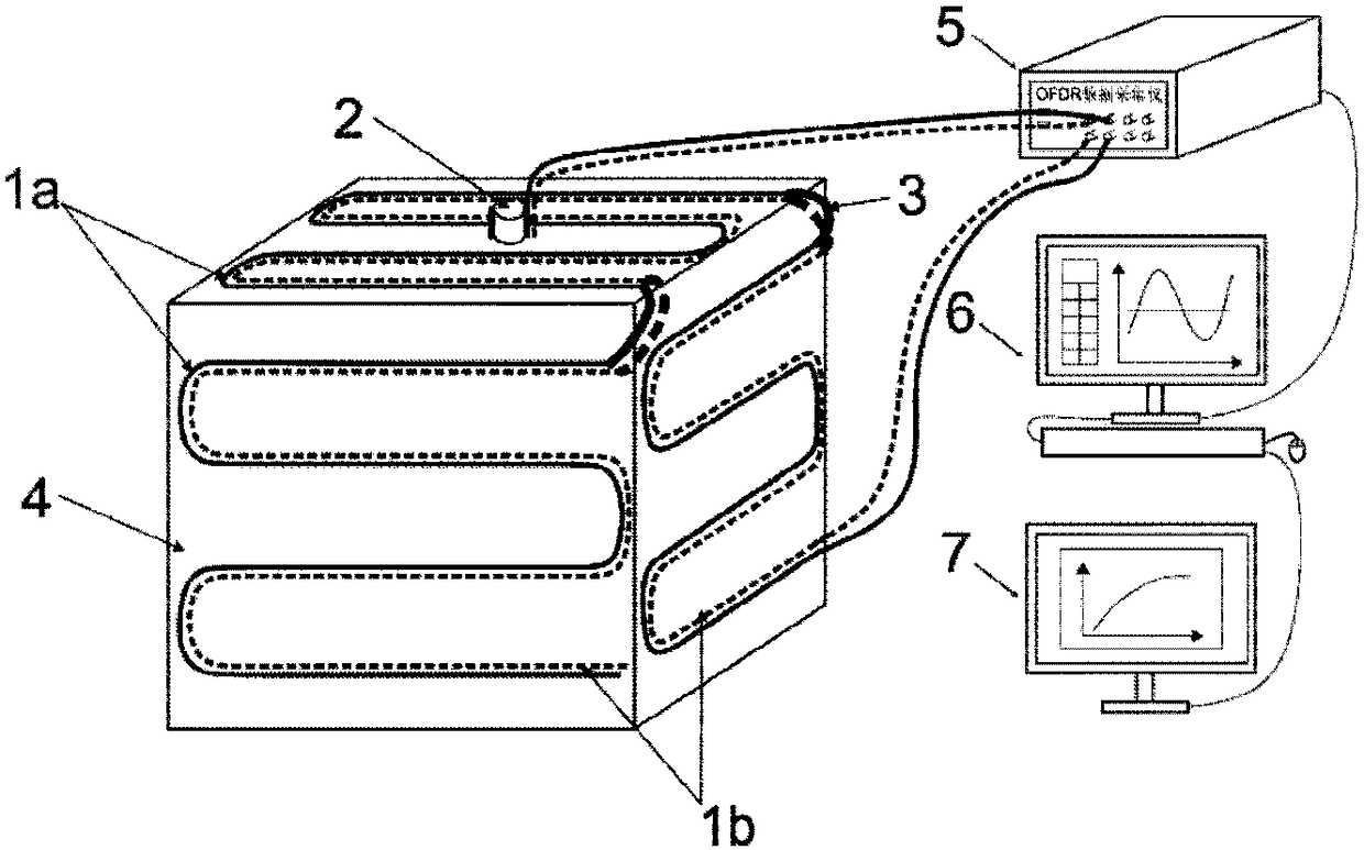
Figure 1 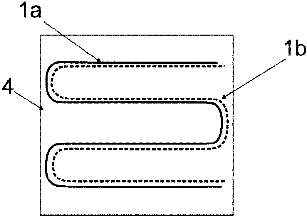
Figure 2 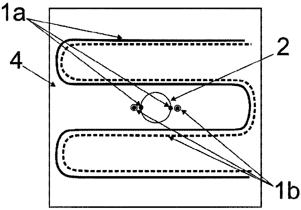
Figure 3
Abstract
Description
technical field
[0001] The invention relates to the field of civil engineering testing, in particular to a steel bar corrosion and deformation monitoring system based on OFDR technology and a use method. Background technique
[0002] With the rapid development of construction technology, the durability of reinforced concrete structures has attracted more and more attention. Corrosion of steel bars will reduce the bonding force between steel bars and concrete, and at the same time cause tensile cracking of concrete, which becomes an important reason for the durability damage of reinforced concrete structures. At present, electrochemical methods are often used to study the corrosion process of steel bars. How to conveniently and effectively monitor the deformation of steel bars and concrete during the corrosion process has become a difficult point. Deformation monitoring is an important aspect of corrosion testing. At present, traditional methods such as resistive strain gaug...
Examples
Embodiment Construction
[0026] like figure 1 As shown, 1a is the strain sensing fiber, and 1b is the temperature compensation fiber, which are evenly arranged on the side and upper surface of the test block in an S-shape. When laying, the sensing fiber should be close to the surface of the test block. The strain-sensing optical fiber 1a is pre-stretched and laid in the pre-carved groove on the surface of the steel bar 2, and the temperature-compensating optical fiber 1b is placed naturally without applying force. A certain length should be reserved at the beginning of the laid sensing optical fiber, so that it can be led out and connected to the data acquisition instrument in the later test, and the optical fiber connection is reinforced and protected with a thermal expansion tube. 2 is the steel bar; 3 is the armored sheath, which protects the bending of the optical fiber; 4 is the 1m x 1m x 1m concrete test block, which is used as the carrier of the corrosion of the steel bar; 5 is the optical fibe...