
Nondestructive testing method for film coating debonding defect based on grating laser ultrasonic sound spectrum

A laser ultrasonic, non-destructive testing technology, applied in the use of sound waves/ultrasonic waves/infrasonic waves to analyze solids, use sound waves/ultrasonic waves/infrasonic waves for material analysis, measuring devices, etc. Detection and other problems, achieve high sensitivity and spatial resolution, and solve the effect of surface blind spots

Active Publication Date: 2021-11-02
XI AN JIAOTONG UNIV
View PDF6 Cites 2 Cited by
  • Summary
  • Abstract
  • Description
  • Claims
  • Application Information

AI Technical Summary

Problems solved by technology

When the traditional ultrasonic testing method detects the debonding defect of the coating, the body wave is generally used to detect the debonding defect. This method will cause signal confusion between the initial wave and the reflected wave when the coating is thin. Difficult to distinguish, resulting in surface blind spots in the detection of coating debonding defects, and effective detection of debonding defects in thin film coatings. At the same time, there are several shortcomings such as the inability to achieve complete non-contact measurement, and the inability to realize detection in harsh environments such as high temperatures. , resulting in many limitations in the current detection process of coating debonding defects

Method used


Image

  • Nondestructive testing method for film coating debonding defect based on grating laser ultrasonic sound spectrum
  • Nondestructive testing method for film coating debonding defect based on grating laser ultrasonic sound spectrum
  • Nondestructive testing method for film coating debonding defect based on grating laser ultrasonic sound spectrum

Examples


Embodiment Construction

[0015] The present invention will be described in further detail below in conjunction with the accompanying drawings and specific embodiments.

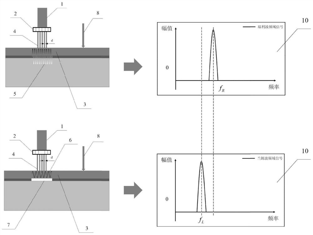
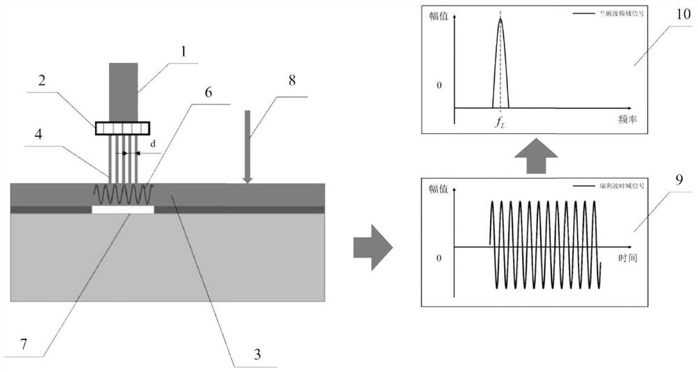
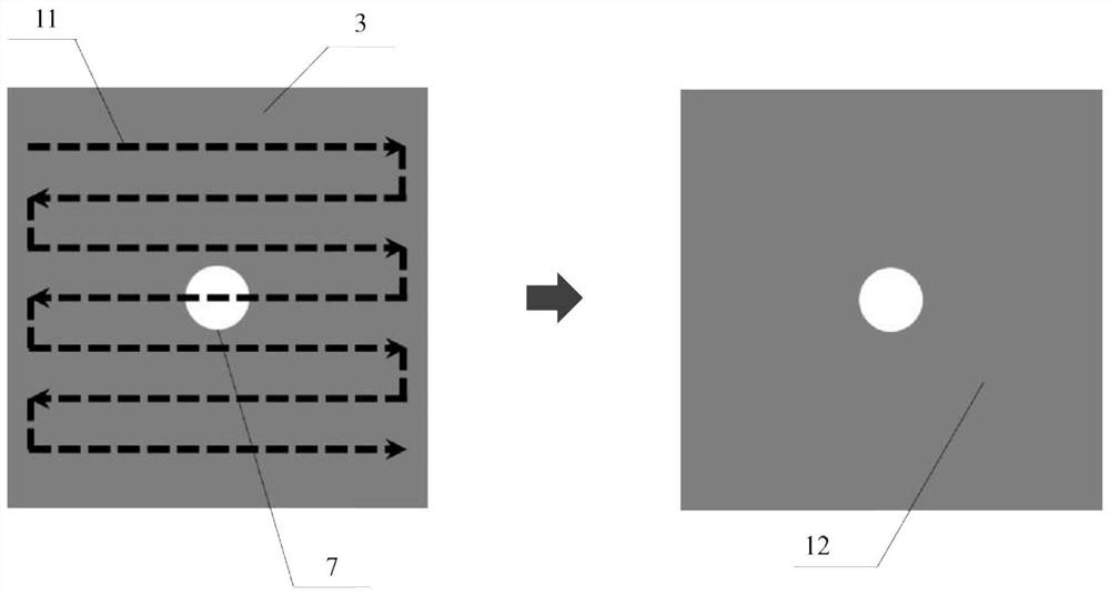
[0016] The present invention proposes a non-destructive testing method for debonding defects of thin film coatings based on grating laser ultrasonic sound spectrum, such as figure 1 shown. First, the high-energy pulsed laser beam 1 irradiated onto the surface of the film coating structure 3 to be tested is used to form a grating laser spot 4 with a period of d by using an equidistant optical mask or a microlens array 2, and the surface of the film coating structure to be tested is thermally expanded during the period Under excitation, an ultrasonic wave corresponding to the wavelength λ (λ=d) is excited. When there is no debonding defect in the measured area, the excited ultrasonic wave is Rayleigh wave 5; when there is a disbonding defect 7 in the measured area, the excited ultrasonic wave The energy is confined to a region of only ...


PUM


Abstract

The invention discloses a nondestructive testing method for a film coating debonding defect based on a grating laser ultrasonic sound spectrum. The method comprises the following steps that a strong pulse laser beam is irradiated to a surface of a detected film coating structure through an optical mask plate or a microarray lens to form periodically distributed tiny grating-shaped laser spots, and ultrasonic waves with fixed wavelength are excited in a detected area; when the detected area has no debonding defect, the excited ultrasonic wave is a Rayleigh wave, and when the detected area has the debonding defect, a Lamb wave is generated; under the condition of certain wavelength, as the wave velocities of the two waves are different, the corresponding frequencies of the two waves are different, the laser ultrasonic detection unit is adopted to receive the generated ultrasonic signals near the detected area, the center frequency of the ultrasonic signals is obtained, and whether the debonding defect exists or not can be judged according to a center frequency value of the detected signals; and the size of the debonding defect can be judged through scanning detection, and the debonding defect can be imaged.

Description

technical field [0001] The invention relates to a nondestructive detection method for debonding defects of coatings, in particular to a nondestructive detection method for debonding defects of thin film coatings based on grating laser ultrasonic sound spectrum. Background technique [0002] The coating is a solid continuous film structure sprayed on the surface of the substrate material for the purpose of protection, heat insulation and wear resistance. It is widely used in high-temperature structural components such as aero engines and heavy gas turbines. It is deposited on high-temperature resistant alloy substrates The surface of the material reduces the operating temperature of the component and prolongs its service life. However, in the long-term service process, the internal debonding defect of the coating system (coating + substrate) is an important cause of coating failure. As the working time of the coating increases, debonding defects will initiate and expand insi...

Claims


Application Information

Patent Timeline
IPC IPC(8): G01N29/04G01N29/06G01N29/12G01N29/46G06F17/14
CPCG01N29/041G01N29/069G01N29/12G01N29/46G06F17/14
Inventor 裴翠祥钱程寇兴
Owner XI AN JIAOTONG UNIV
Learn More