Soil pressure measuring method with variable measuring range based on Bragg fiber grating

A technology of Bragg optical fiber and soil pressure, which is applied in the direction of measuring force, measuring device, and measuring the change force of the optical properties of the material when it is stressed, and can solve the problem of affecting the mechanical properties of the measured object and affecting the settlement of tunnel excavation It is difficult to solve problems such as calculation, strain and deformation of the measured object, and achieve the effect of simple structure, high safety and meeting the measurement requirements

Active Publication Date: 2018-09-11
湖北省路桥集团有限公司 +1
View PDF4 Cites 14 Cited by
  • Summary
  • Abstract
  • Description
  • Claims
  • Application Information

AI Technical Summary

Problems solved by technology

[0002] The existing local pressure measurement on the soil surface uses an electromagnetic displacement meter, which can measure the displacement between the upper and lower surfaces of the measured object, but it is difficult to accurately measure the local strain and deformation in the middle of the measured object on both sides
However, the local small displacement will affect the calculation of the mechanical properties of the measured object. For example, the mechanical properties of the local small strain of the soil are related to the calculation of the deformation of the adjacent buildings caused by the excavation of the foundation pit, and it will also affect the calculation of the deformation caused by the excavation of the tunnel. Settlement calculation

Method used


Image

  • Soil pressure measuring method with variable measuring range based on Bragg fiber grating
  • Soil pressure measuring method with variable measuring range based on Bragg fiber grating
  • Soil pressure measuring method with variable measuring range based on Bragg fiber grating

Examples


Embodiment Construction

[0023] In order to make the object, technical solution and advantages of the present invention clearer, the present invention will be further described in detail below in conjunction with the accompanying drawings and embodiments. It should be understood that the specific embodiments described here are only used to explain the present invention, not to limit the present invention. In addition, the technical features involved in the various embodiments of the present invention described below can be combined with each other as long as they do not constitute a conflict with each other.

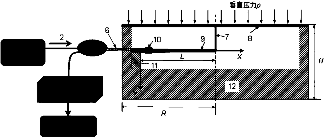
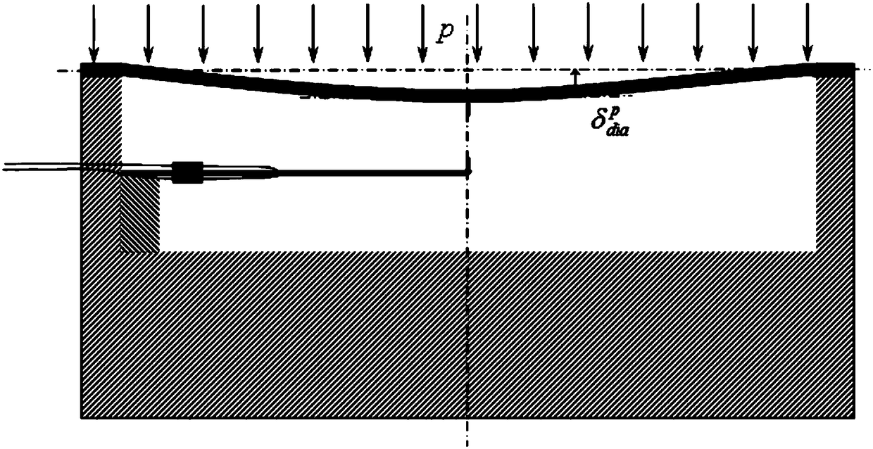
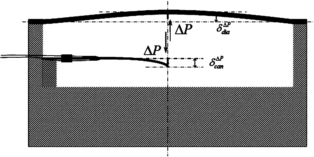
[0024] The present invention utilizes the fiber Bragg grating sensor 10, installs the fiber Bragg grating sensor 10 on the surface of the cantilever beam 9, connects with the film 8 through the rigid dowel 7, and fixes it on the surface of the measured object. When the measured object is subjected to an external load , its deformation will cause the deformation of the film 8, the axial deformati...


PUM


Abstract

The invention belongs to the field of a soil internal pressure measuring method, and discloses a soil pressure measuring method with a variable measuring range based on a Bragg fiber grating. The method includes following steps: (1) selecting materials and dimensions of a cantilever beam and a film according to the dimension of a measured object and a measuring requirement; (2) installing a Braggfiber grating sensor on the cantilever beam to enable the Bragg fiber grating sensor and the cantilever beam to be tightly combined, connecting a free end of the cantilever beam and the film togetherthrough a rigid dowel bar, and connecting the Bragg fiber grating sensor to an optical fiber signal analysis processing device through an optical fiber; (3) fixing a fixed end of the cantilever beam to a sensor cavity, and placing a whole soil pressure transducer in the measured object; and (4) continuously measuring a strain value of the Bragg fiber grating sensor, and calculating a local pressure of the measured object. According to the method, the problem of precision measurement of soil pressure of different measuring ranges in the soil can be solved, the measuring requirement of the wide-span measuring range can be satisfied, the measuring precision of the sensor is high, and the security is high.

Description

technical field [0001] The invention belongs to the field of soil internal pressure measurement methods, and more specifically relates to a variable-range soil pressure measurement method based on Bragg fiber gratings. Background technique [0002] The existing local pressure measurement on the soil surface uses an electromagnetic displacement meter, which can measure the displacement between the upper and lower surfaces of the measured object, but it is difficult to accurately measure the local strain and deformation in the middle of the measured object on both sides. However, the local small displacement will affect the calculation of the mechanical properties of the measured object. For example, the mechanical properties of the local small strain of the soil are related to the calculation of the deformation of the adjacent buildings caused by the excavation of the foundation pit, and it will also affect the calculation of the deformation caused by the excavation of the tun...

Claims


Application Information

Patent Timeline
Patent Type & Authority Applications(China)
IPC IPC(8): G01L1/24
CPCG01L1/246
Inventor 周乐木殷源李伟业谢超孙开武徐东升周方圆
Owner 湖北省路桥集团有限公司
Why Eureka
Try Eureka