Soil Sampler

A soil sample and control panel technology, which is applied in the preparation, sampling, and instrumentation of test samples, can solve the problems of low cutting precision, uneven size, and poor uniformity, and achieve convenient operation, simple control methods, and easy-to-use Effect

Active Publication Date: 2020-09-08
中煤江苏勘测设计研究院有限公司
View PDF10 Cites 0 Cited by
  • Summary
  • Abstract
  • Description
  • Claims
  • Application Information

AI Technical Summary

Problems solved by technology

[0004] When preparing samples, the operator needs to cut the columnar soil. The traditional operation method is to cut the soil sample with a wire saw by the operator. The cut soil samples are of different sizes, with poor uniformity and low cutting accuracy. Low

Method used


Image

  • Soil Sampler
  • Soil Sampler
  • Soil Sampler

Examples


Embodiment 1

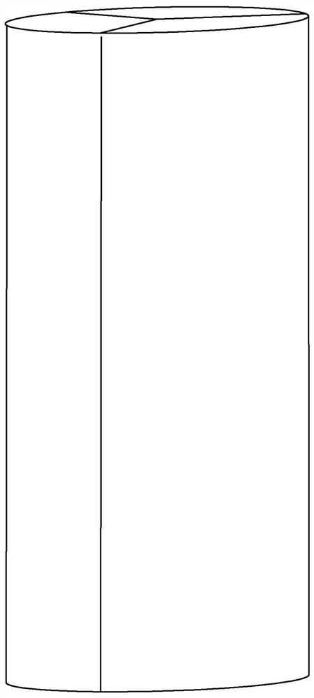
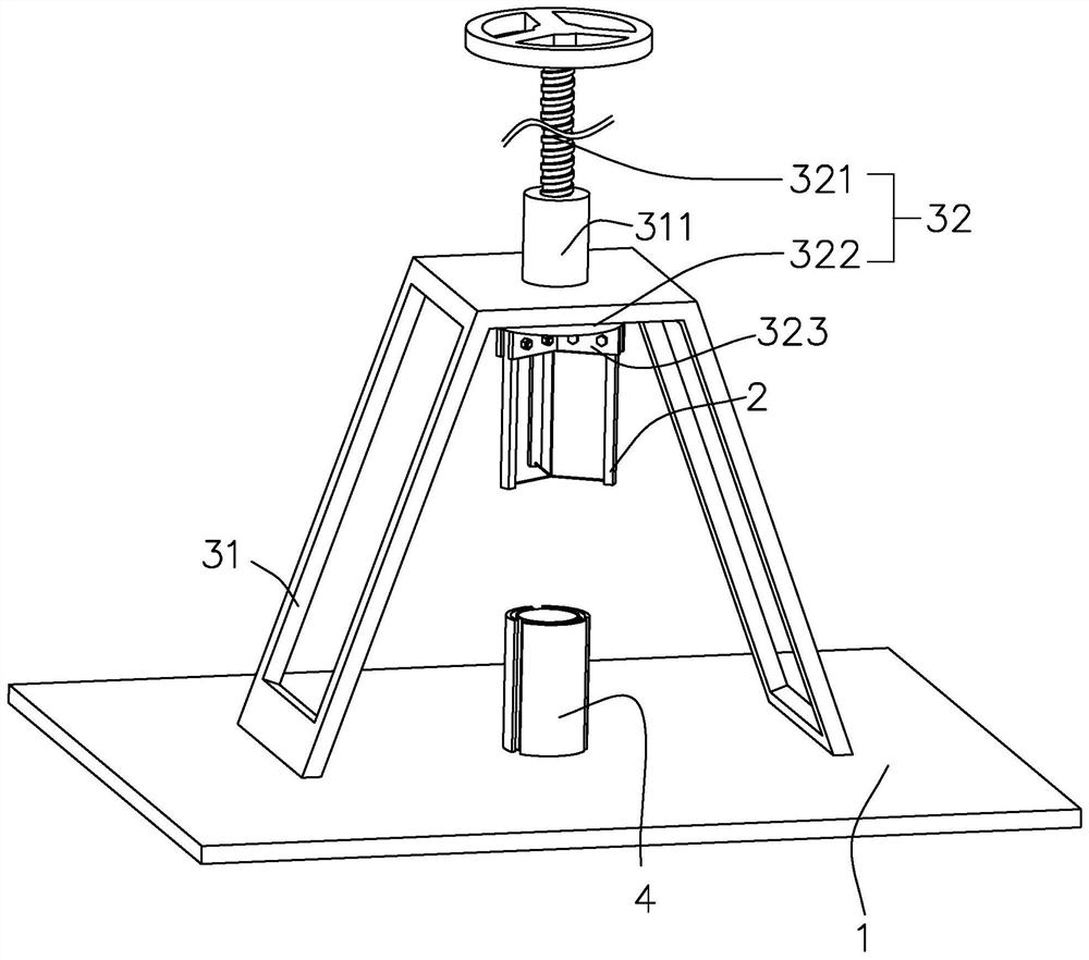
[0040] A soil sample preparation device, such as figure 2 , including a base 1, a wire saw 2 and a control mechanism. There are three wire saws 2 which are movably connected to the base 1 , and the control mechanism controls the movement of the wire saws 2 . The control mechanism controls the wire saws 2 to perform linear motion, the angle between two adjacent wire saws 2 is 120°, and the three wire saws 2 divide the circumference into equal parts to ensure the uniformity of the cut soil samples. The length of the wire saw 2 is greater than the height of the columnar soil, so as to ensure the cutting effect of the wire saw 2 on the columnar soil and ensure the cutting quality.

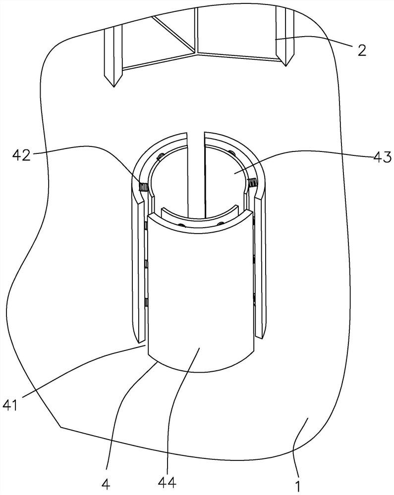
[0041] Such as figure 2 , The base 1 is provided with a limit cylinder 4 for limiting the position of the columnar soil, and the limit cylinder 4 cooperates with three wire saws 2 . The columnar soil is placed in the limiting cylinder 4, and the three wire saws 2 cut the columnar soil. When the th...

Embodiment 2

[0051] The difference between embodiment two and embodiment one is that the control mechanism is different: as Figure 5 and Figure 6 , the control mechanism includes a control coil wire 33 , a sliding block 34 and a control handle 35 . The control wire 33 is rotatably connected to the bottom of the base 1 , and the control wire 33 and the limit cylinder 4 are arranged coaxially. The sliding block 34 and the control handle 35 are connected with the control wire 33 .

[0052] Such as Figure 6 The lower surface of the control coil wire 33 is provided with a rotating tooth groove 332, the control handle 35 is rotatably connected to the bottom of the control coil wire 33, and the end of the control handle 35 is provided with a rotating gear 351 meshing with the rotating tooth groove 332. The axis of the control wire 33 is perpendicular to the axis of the rotating gear 351 . The operator rotates the control handle 35, and the control handle 35 drives the control coil wire 33 ...


PUM


Abstract

The invention relates to the technical field of soil sample test and discloses a soil sampler. The soil sampler includes a base glidingly connected three wire saws. The length of the steel saws is higher than the height of soil samples. The three wire saws are evenly distributed along the circumferential direction, and the angle between two adjacent wire saws is 120 degrees. A control mechanism isarranged on the base to control the movement of the wire saws. The soil samples are put on the base. A operator controls the movement of the wire saws through the control mechanism, with three wiresaws moving toward columnar soil. The angle between the two adjacent wire saws is always 120 degrees. The three wire saws cut the columnar soil into the soil samples of three fan-shaped pieces. Because the angle of the two adjacent wire saws is always 120 degrees, the center angle of the soil samples is also 120 degrees. The three soil samples are of the same size and the precision of the cut soilsamples is higher. The operator can cut the soil samples only by controlling the control mechanism, which is easy to operate and convenient to use.

Description

technical field [0001] The invention relates to the technical field of soil sample detection, in particular to a soil sample preparation device. Background technique [0002] Soil environment monitoring refers to the determination of environmental quality (or pollution degree) and its changing trend through the determination of representative values ​​of factors affecting soil environmental quality. [0003] Soil testing is divided into soil sampling, sample preparation and testing. Such as figure 1 , the operator samples the soil through the soil ring knife, and the soil taken out by the soil ring knife is generally cylindrical in shape as the ring knife. The operator cuts the obtained soil sample, and cuts the columnar soil into three equal fan-shaped soil samples. After sample preparation, the operator places the soil sample on the operating table and tests the soil sample. Detect parameters such as nutrients and moisture of soil samples. [0004] When preparing samp...

Claims


Application Information

Patent Timeline
Patent Type & Authority Patents(China)
IPC IPC(8): G01N1/28
CPCG01N1/286G01N2001/2873
Inventor 吴卫华汤庆声
Owner 中煤江苏勘测设计研究院有限公司
Why Eureka
Try Eureka