
Tool for gearbox machining

A gearbox and gear technology, which is applied in metal processing and other directions, can solve problems such as difficult to realize, unfavorable rational use of resources, complicated operation process, etc., and achieve the effects of improving turning efficiency, ensuring stability, and enhancing sealing

Active Publication Date: 2018-09-14
重庆市耀植机械有限责任公司
View PDF11 Cites 2 Cited by
  • Summary
  • Abstract
  • Description
  • Claims
  • Application Information

AI Technical Summary

Problems solved by technology

On the one hand, this method makes the operation process more complicated. On the other hand, iron filings and dust on the ground will be stained during the overturning process of the gearbox. Adjusting the clearance is not conducive to the rational use of resources. In addition, if the height of the factory building is limited, the process of lifting the axle and then raising it to a certain height to put it into the supporting cylinder becomes difficult to achieve.

Method used


Image

  • Tool for gearbox machining
  • Tool for gearbox machining
  • Tool for gearbox machining

Examples


Embodiment Construction

[0022] The present invention will be described in further detail below by means of specific embodiments:

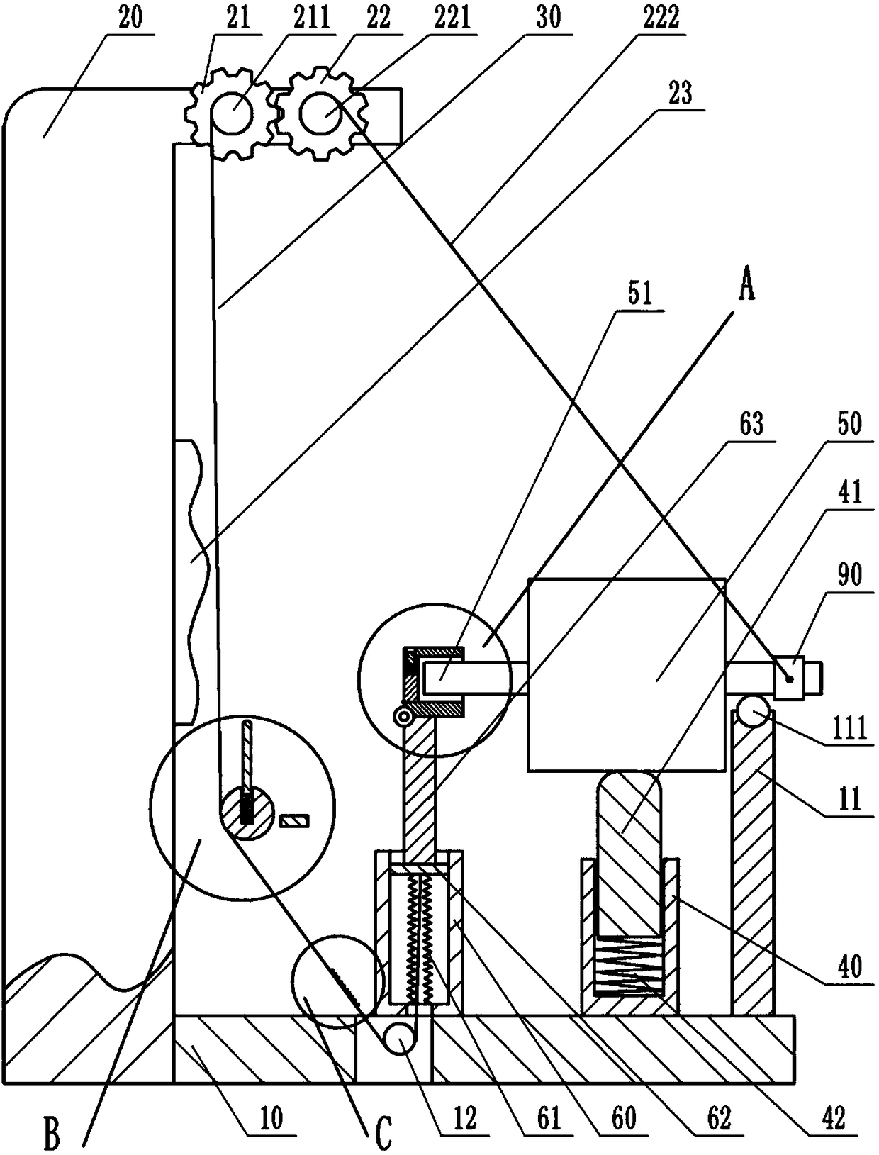
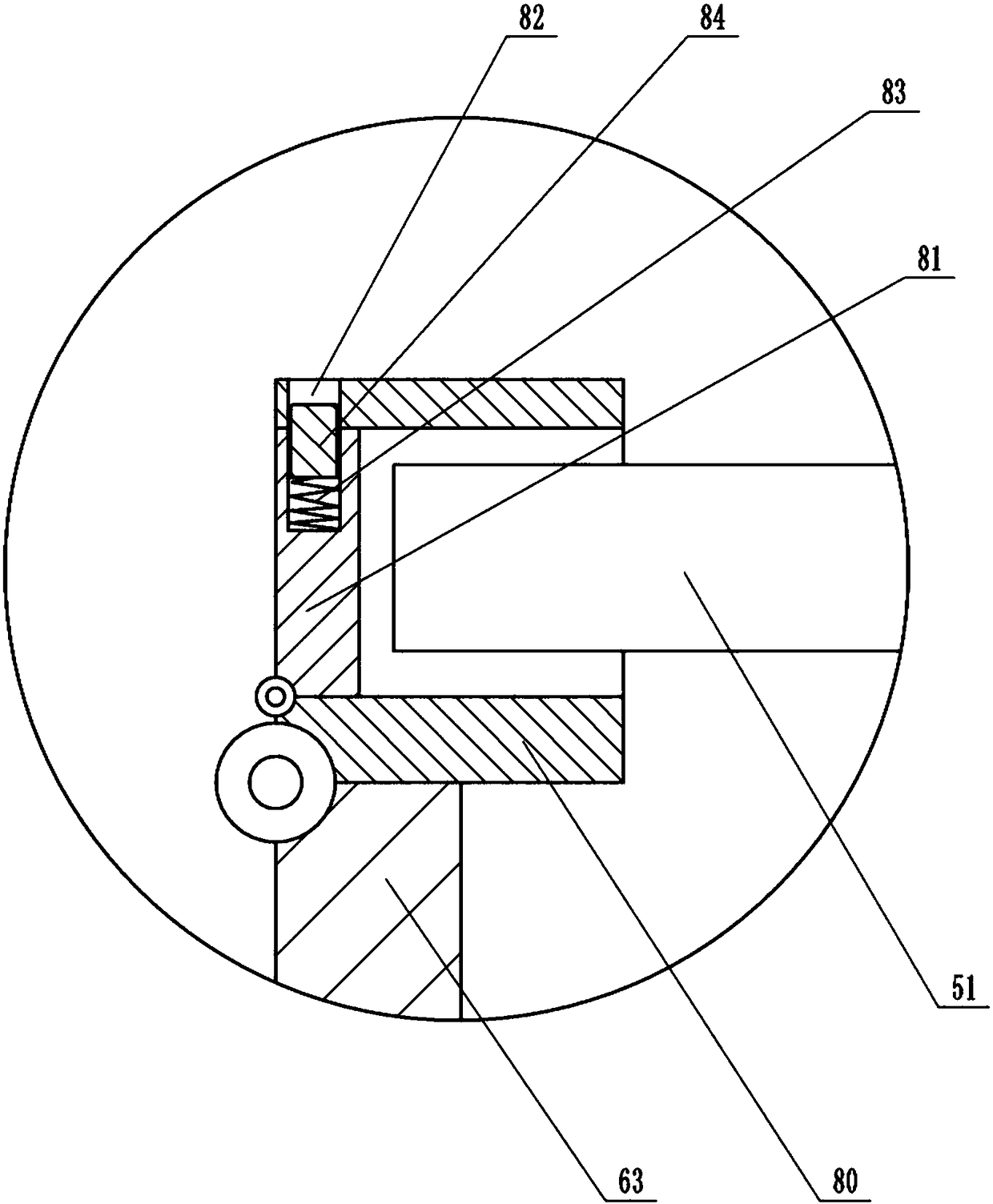
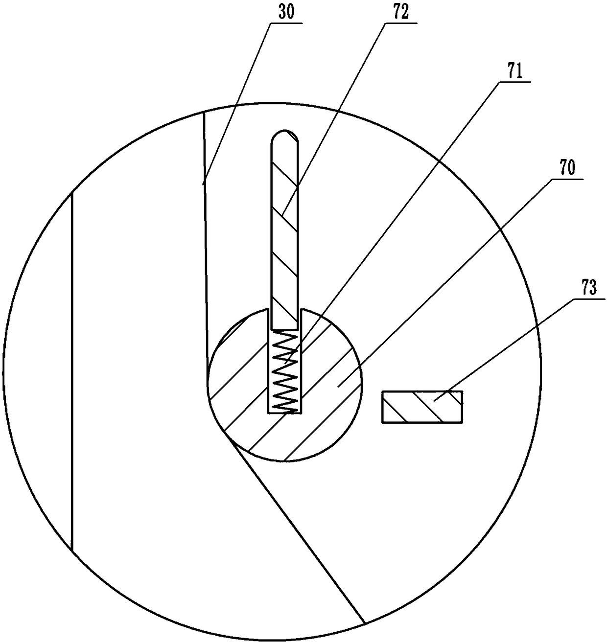
[0023] Instructions attached Figures 1 to 5 The reference numerals in include: mounting seat 10, column 11, ball 111, frame 20, second gear 21, rewinding wheel 211, first gear 22, wire wheel 221, stay wire 222, buffer pad 23, stay cord 30 , protruding tooth 31, limit cylinder 40, top column 41, third spring 42, gear box 50, axle 51, piston cylinder 60, bellows 61, piston 62, pillar 63, roller 70, second spring 71, top Rod 72 , limit block 73 , annular groove 74 , locking teeth 75 , turning cylinder 80 , closing door 81 , through groove 82 , first spring 83 , connecting block 84 , and collar 90 .

[0024] like figure 1 As shown, the gear box processing tooling includes a frame 20, an installation unit, a push-off unit, a pulling unit and a top unit, and the installation unit includes a mounting seat 10, a collar 90, and a column 11 and For the turning mechanism, the co...


PUM


Abstract

The invention belongs to the technical field of workpiece clamping devices or workpiece positioning devices and particularly discloses a tool for gearbox machining. The tool comprises a rack, a mounting unit, a jacking unit and a pulling unit. The mounting unit comprises a mounting seat, a lantern ring, a vertical column and a turning-over mechanism; the turning-over mechanism comprises a piston cylinder and a piston, a supporting column is arranged on the piston, a turning-over cylinder is hinged to the supporting column, and a closing door is hinged to the turning-over cylinder; and a sliding groove is formed in the side wall of the closing door, and a connecting block is slidably connected in the sliding groove. The jacking unit comprises a rotating roller;and clamping teeth are arranged on the surface of the rotating roller, a clamping groove is formed in the rotating roller, a jacking rod is slidably connected in the clamping groove, and a second spring is connectedbetween the jacking rod and the clamping groove. The pulling unit comprises a first gear and a second gear; a wire wheel is arranged at the rotating center of the first gear, and a winding wheel with a wound pullingrope is arranged at the rotating center of the second gear; and convex teeth are arranged on the side, close to the piston cylinder, of the pulling rope. The tool is used for adjusting the box clearance between the gears, the whole adjusting process is standard, simple and convenient, and the easy operation property is achieved.

Description

technical field [0001] The invention belongs to the technical field of workpiece clamping devices or positioning devices, and in particular relates to a gear box processing tooling. Background technique [0002] The usual way to adjust the clearance of the gearbox is: turn the gearbox to a vertical position, then put it into a special support cylinder tooling, and use a jack to lift the axle to adjust the clearance. Currently, the turning of the gearbox is done on a rubberized floor and then hoisted into a support cylinder. On the one hand, this method makes the operation process more complicated. On the other hand, iron filings and dust on the ground will be stained during the overturning process of the gearbox. Adjusting the clearance is not conducive to the rational use of resources. In addition, if the height of the factory building is limited, the process of lifting the axle and then raising it to a certain height to put it into the support cylinder becomes difficult t...

Claims


Application Information

Patent Timeline
Patent Type & Authority Applications(China)
IPC IPC(8): B23Q7/00
CPCB23Q7/00
Inventor 钟志希
Owner 重庆市耀植机械有限责任公司
Learn More