Tire smashing device

A crushing device and tire technology, applied in recycling technology, mechanical material recycling, plastic recycling, etc., to achieve the effect of strong impact, saving processing time, and increasing motion potential energy

Inactive Publication Date: 2018-09-14
NINGBO HAIMAN AUTOMOTIVE TECH CO LTD
View PDF5 Cites 0 Cited by
  • Summary
  • Abstract
  • Description
  • Claims
  • Application Information

AI Technical Summary

Problems solved by technology

[0005] The present invention intends to provide a tire crushing device to solve the problems of how to avoid the rolling between the tire and the crushing cylinder and how to prolong the service period of the crushing cylinder

Method used


Image

  • Tire smashing device
  • Tire smashing device

Examples


Embodiment Construction

[0024] Further detailed explanation through specific implementation mode below:

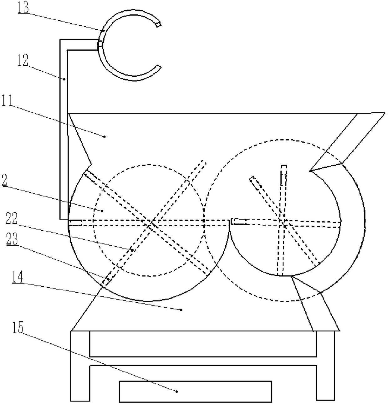
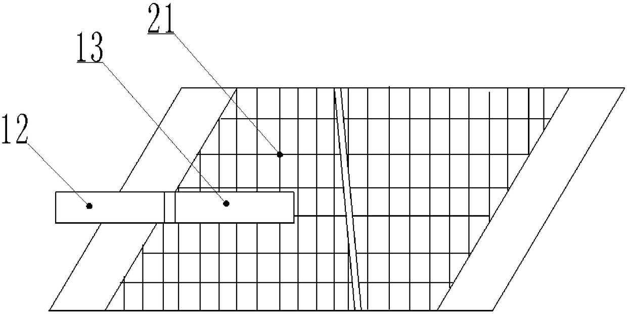
[0025] The reference numerals in the accompanying drawings of the specification include: feed inlet 11 , rotating arm 12 , clamp 13 , discharge outlet 14 , receiving trough 15 , crushing cylinder 2 , blade 21 , support rod 22 , and impact member 23 .

[0026] Such as figure 1 The shown tire crushing device includes a hollow shell, which is mounted on a bracket. The upper end of the housing is provided with a feeding port 11, and a clamp 13 is provided above the feeding port 11. The clamp 13 includes two jaws, and the clamp 13 is connected with a third motor. The clamp 13 is welded with a rotating arm 12, which in this embodiment is in an "L" shape. The rotating arm 12 is welded on the housing, the rotating arm 12 is connected with a second motor, the second motor is electrically connected with a button, and the button is welded at the end of the clamping jaw at a high place, and the second moto...


PUM


Abstract

The invention discloses a tire smashing device. The device comprises a shell, a feeding port is formed in the upper part of the shell, a clamp is arranged above the feeding port, is connected with a third motor, and is connected with a rotating arm, the rotating arm is connected on the shell, a second motor is connected on the rotating arm, and is electrically connected with a button, and the button is located at the end parts of clamping jaws, and is used for controlling the second motor to stop the rotating arm from rotating; a plurality of smashing cylinders which are transversely arrangedside by side are rotationally connected in the shell, each smashing cylinder is in a circular truncated cone shape, the directions of the small-diameter ends on the adjacent smashing cylinders are opposite, criss-cross cutting edges are arranged on the outer walls of the smashing cylinders, and each smashing cylinder is hollow; and hollow supporting rods are arranged in the smashing cylinders, thetwo ends of the supporting rods are connected with the inner walls of the smashing cylinders, and impact pieces with the weak magnetism are arranged in the supporting rods. By adopting the technicalscheme, the service period of each smashing cylinder can be protected, the equipment investment cost can be reduced, a tire can also be fully smashed, and the working efficiency can be improved.

Description

technical field [0001] The invention relates to the technical field of tire recycling and processing, in particular to a tire crushing device. Background technique [0002] In the recycling process of waste tires, it is necessary to break the waste tires into small pieces of rubber. The waste tire coarse shredder currently in use is to put the whole waste tire on the whole tire conveyor and send it to the tire crusher for crushing. After repeated rotation of the circular screen and repeated crushing of the cutter head, it is finally discharged from the screen. The rubber block, the rubber block then enters the crushing of the next stage crusher. The disadvantages of the shredder that crushes waste tires at one time are: the machine is easy to jam, the output is low, the knives are easily damaged, and it is easy to cause damage to the reducer and other components. [0003] The patent document whose publication number is CN105345946A discloses a tire shredder, which includes...

Claims


Application Information

Patent Timeline
Patent Type & Authority Applications(China)
IPC IPC(8): B29B17/04
CPCB29B17/0412B29B2017/044Y02W30/52Y02W30/62
Inventor 卢文斌
Owner NINGBO HAIMAN AUTOMOTIVE TECH CO LTD
Why Eureka
Try Eureka