
Unmanned aerial vehicle (UAV) and UAV stable landing buffer device

A technology of buffer device and drone, applied in the field of drone, can solve the problem of unsatisfactory design of shock absorption buffer device, etc., and achieve the effect of ingenious design

Active Publication Date: 2018-09-14
河南金迈科科技集团有限公司
View PDF3 Cites 1 Cited by
  • Summary
  • Abstract
  • Description
  • Claims
  • Application Information

AI Technical Summary

Problems solved by technology

[0004] When the multi-rotor UAV lands and touches the ground, it is necessary to perform shock absorption to protect the fuselage. At present, there are few such shock-absorbing and buffering devices, and some existing shock-absorbing and buffering devices are not ideal. Therefore, it is necessary to design a A buffer device that is more reasonable and has better shock absorption and buffering effects

Method used


Image

  • Unmanned aerial vehicle (UAV) and UAV stable landing buffer device
  • Unmanned aerial vehicle (UAV) and UAV stable landing buffer device
  • Unmanned aerial vehicle (UAV) and UAV stable landing buffer device

Examples


Embodiment 1

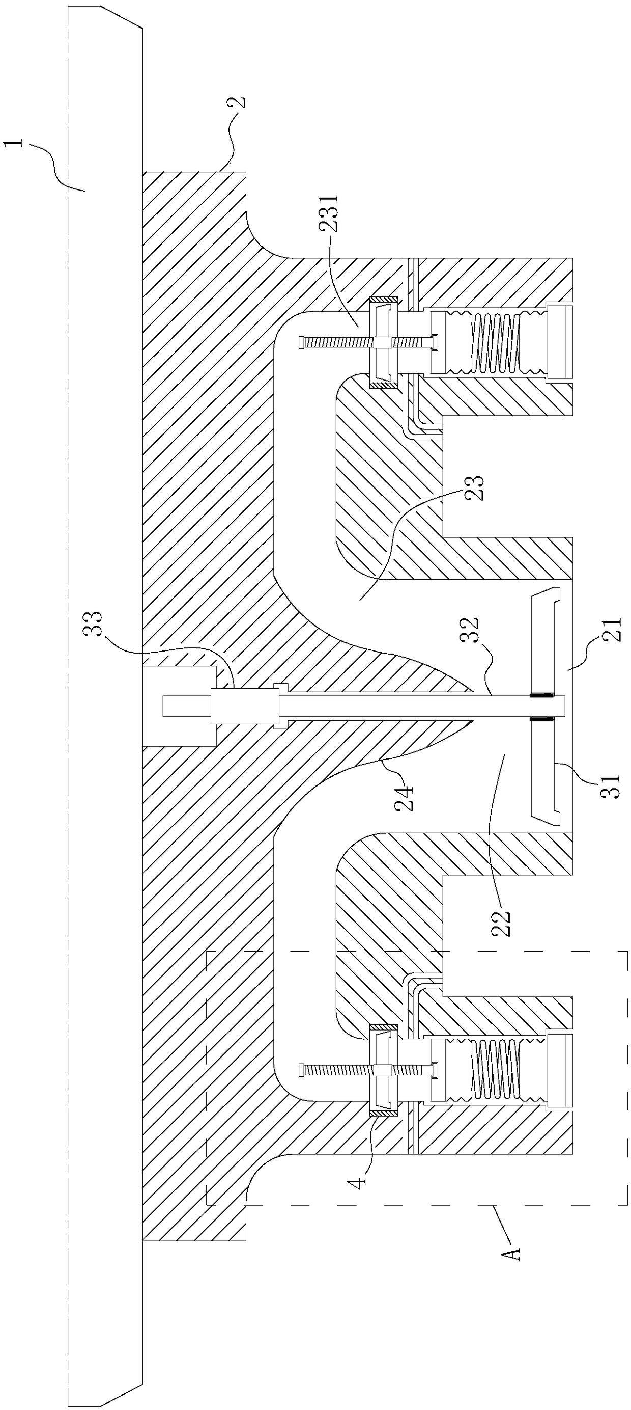
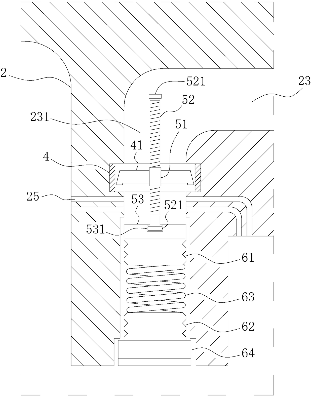
[0030] This embodiment provides a stable landing buffer device for drones, which includes a housing 2, a first fan wheel 31, a fan box 4, a threaded sleeve 51, a threaded rod 52, a connecting plate 53 and a buffer foot.

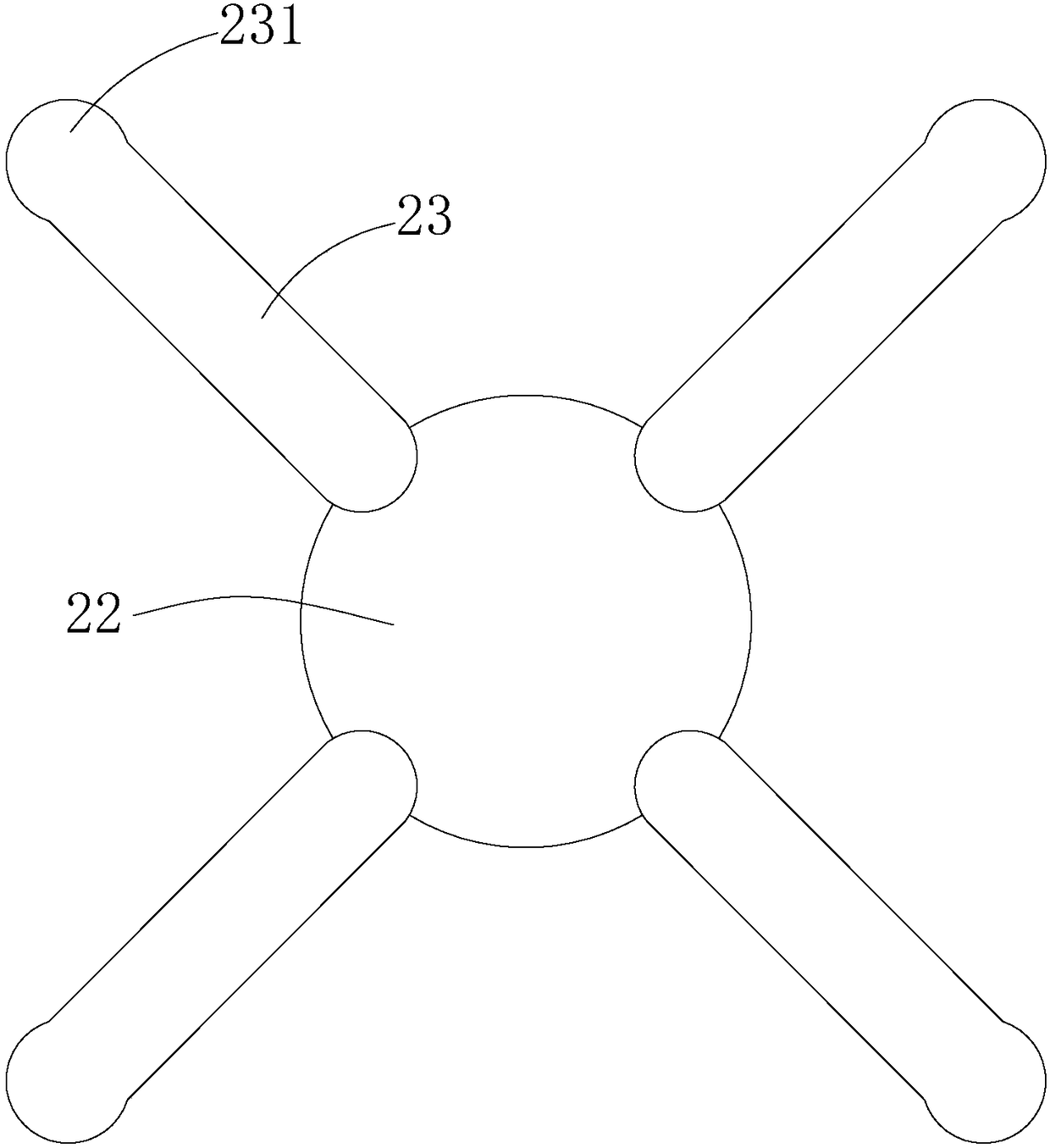
[0031] The bottom of the housing 2 is provided with an air inlet 21, above the air inlet 21 is a main air duct 22, and above the main air duct 22 are communicated with four secondary air ducts 23, and the four secondary air ducts 23 respectively extend around, The extension direction of the end section 231 of the secondary air duct 23 is vertically downward.

[0032] The first wind impeller 31 is arranged laterally at the air inlet 21 , and the first wind impeller 31 can be driven to rotate by the airflow.

[0033] The number of the fan blade boxes 4 is four, which are respectively fixed in the end section 231 of the secondary air duct 23 extending vertically downwards corresponding to each secondary air duct 23, and the fan blade boxes 4 are located at the u...

Embodiment 2

[0049] This embodiment provides an unmanned aerial vehicle, the bottom of the unmanned aerial vehicle body 1 is installed with the unmanned aerial vehicle stable landing buffer device described in the first embodiment.


PUM


Abstract

The invention discloses an unmanned aerial vehicle (UAV) and a UAV stable landing buffer device. The UAV stable landing buffer device comprises a shell, a first wind impeller, four wind impeller boxes, thread bushings, threaded rods, connecting plates and four buffer feet, wherein an air inlet is formed in the bottom of the shell, a main air duct is arranged on the air inlet, four secondary air ducts extending to the periphery are arranged on the main air duct in a communicating way, and the tail sections of the secondary air ducts vertically extend downwards; the first wind impeller is transversely arranged at the air inlet and is driven to rotate by means of airflow; the four wind impeller boxes are respectively and correspondingly fixed at the tail sections of the four secondary air ducts, and are positioned at the upper part positions in the tail sections; the thread bushings are fixed in the centers of second wind impellers in the wind impeller boxes; the thread bushings sleeve the threaded rods in a threaded way and are matched with the threaded rods by means of threads; the connecting plates are connected with the bottom ends of the threaded rods; the four buffer feet respectively correspond to the connecting plates and are fixed at the lower parts of connecting parts. When the UAV lands, a driving force can be generated by means of the upstream airflow, and the buffer feet are then pushed out by driving the threaded rods to move, so that the device is enabled to enter a buffer state.

Description

technical field [0001] The invention relates to the field of unmanned aerial vehicles, in particular to a device located at the bottom of the unmanned aerial vehicle and capable of buffering and protecting when landing. Background technique [0002] UAV is an unmanned aircraft controlled by radio remote control equipment and its own program control device. Civilian UAV has important applications in aerial photography, agriculture, plant protection, disaster relief and other fields. [0003] A multi-rotor UAV is a special unmanned helicopter with three or more rotor shafts. It drives the rotor through the rotation of the motor on each axis, thereby generating thrust. By changing the relative speed between different rotors, the magnitude of the single-axis propulsion can be changed, thereby controlling the trajectory of the aircraft. [0004] When the multi-rotor UAV lands and touches the ground, it is necessary to perform shock absorption to protect the fuselage. At present,...

Claims


Application Information

Patent Timeline
IPC IPC(8): B64C25/58B64C25/62
CPCB64C25/58B64C25/62
Inventor 王娟
Owner 河南金迈科科技集团有限公司
Learn More