Piling device and method

A technology of piling device and pile hammer, which is applied in the direction of sheet pile wall, building, foundation structure engineering, etc., can solve the problems of difficult adjustment of piling force and hydraulic hammer piling control, poor reliability of the device, large environmental pollution, etc., and achieve frequency and stroke Easy to control, long piling stroke, strong expansion effect

Pending Publication Date: 2018-09-14
HUAZHONG UNIV OF SCI & TECH
View PDF4 Cites 4 Cited by
  • Summary
  • Abstract
  • Description
  • Claims
  • Application Information

AI Technical Summary

Problems solved by technology

[0003] Aiming at the above defects or improvement needs of the prior art, the present invention provides a piling device and a piling method, the purpose of which is to provide a pile foundation construction with a simple structure, convenient operation, adjustable impact force, high efficiency, and low energy consumption. , safe, reliable, pollution-free, and suitable for piling devices in different soils, thereby solving the problems of traditional diesel hammer piling such as large environmental pollution, poor device reliability, difficulty in adjusting piling force and complex control, high cost, and maintenance of hydraulic hammer piling. high cost

Method used


Image

  • Piling device and method
  • Piling device and method

Examples


Embodiment 1

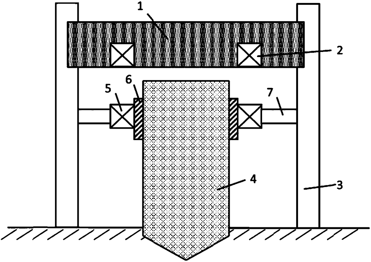
[0042] Such as figure 1 As shown, the overall structure of the piling device according to the embodiment of the present invention includes: a pile hammer 1 , a pile hammer coil 2 , a pile frame 3 , a pile body 4 , a pile body coil 5 , a clamping part 6 , and a beam 7 .

[0043]The pile frame 3 is set on the ground to provide support for the pile hammer 1 and the pile clamping mechanism, and has a guide rail structure; the pile hammer 1 is installed on the pile frame 3, and the pile hammer 1 can move freely on the pile frame 3; the pile hammer coil 2 is fixed on On the pile hammer 1; the pile clamping mechanism includes a clamping part 6 and a beam 7, the clamping part 6 is used to clamp and loosen the pile body 4, the beam 7 is connected with the pile frame 3, and the pile clamping mechanism can move up and down in the guide rail; The pile body coil 5 is fixed on the outside of the clamping part 6 as a whole, and is integrated with the pile body 4 through the pile clamping mec...

Embodiment 2

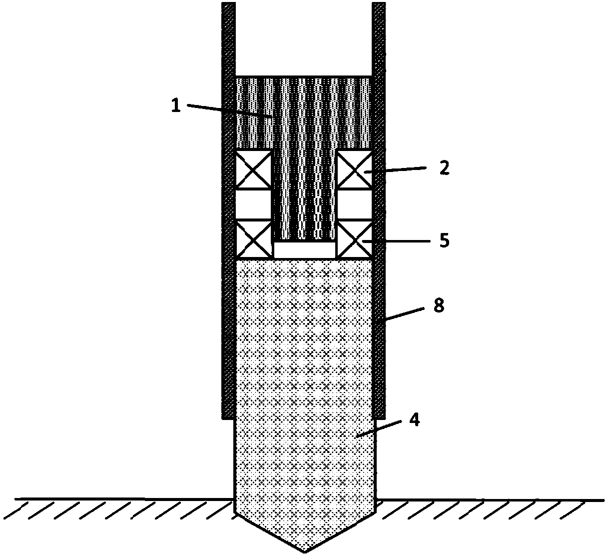
[0052] Such as figure 2 As shown, the overall structure of the piling device according to the embodiment of the present invention includes: a pile hammer 1 , a pile hammer coil 2 , a pile body 4 , a pile body coil 5 , and a guide sleeve 8 .

[0053] The pile hammer 1 is T-shaped and installed on the guide sleeve 8; the pile hammer coil 2 is fastened and connected to the lower part of the pile hammer 1 by bolts; the guide sleeve 8 is equipped with a guide rail structure, and a through hole is opened in the center, and the pile body 4 is located in the through hole, and the guide sleeve 8 can move up or down as a whole; the pile hammer 1 and the pile body 4 can move up and down in the guide sleeve 8; The pile head (that is, the pile cap) part; the pile body coil 5 and the pile hammer coil 2 are coaxially arranged, and the distance is relatively close to ensure that there is sufficient electromagnetic force between the two coils.

[0054] The piling method comprises the steps o...


PUM


Abstract

The invention discloses a piling device and method. The piling device comprises a pile hammer, pile hammer coils, a pile body, pile body coils and a supporting mechanism. The supporting mechanism provides support for the pile hammer and the pile body, so that the pile hammer and the pile body freely move on the supporting mechanism; the pile hammer coils are fixed to the pile hammer; the pile bodycoils make contact with the pile body; the pile body coils and the pile hammer coils are coaxially arranged; and preset distances are reserved between the pile body coils and the pile hammer coils soas to guarantee that electromagnetic force between the pile body coils and the pile hammer coils meets the requirement. The piling device which is simple in structure, convenient to operate, fast inoperation, adjustable in impact force, high in efficiency, small in energy consumption, safe, reliable, free of pollution and suitable for different soil is provided for pile foundation construction.

Description

technical field [0001] The invention belongs to the field of pile foundation construction, and more specifically relates to a piling device and a piling method. Background technique [0002] The hammering pile sinking method mainly overcomes the resistance of the soil to the pile through the impact generated by the falling of the pile hammer, thereby driving the pile into the foundation. Commonly used pile hammers include: diesel hammer and hydraulic hammer. The diesel hammer drives the piston to reciprocate through the fuel explosion to hammer the piling. Its mechanical structure is simple, but the energy transfer rate is low, the reliability of the device is poor, and the maintenance and repair are frequent. At the same time, it is difficult to accurately adjust and control the piling force. It is easy to cause serious environmental pollution, and the working conditions of operators are very bad. The hydraulic hammer mainly drives the impact part through the oil cylinder...

Claims


Application Information

Patent Timeline
Patent Type & Authority Applications(China)
IPC IPC(8): E02D7/08E02D7/14E02D7/16E02D13/04
CPCE02D7/08E02D7/14E02D7/16E02D13/04
Inventor 李亮黄玉杰韩小涛
Owner HUAZHONG UNIV OF SCI & TECH
Why Eureka
Try Eureka