Outdoor heat-dissipation dustproof power distribution cabinet
A power distribution cabinet, dust-proof technology, applied in substation/power distribution device shell, electrical components, substation/switch layout details, etc., can solve problems such as easy to be affected by moisture, hidden safety hazards, slow cooling speed, etc., and avoid corrosion of circuits Effect
- Summary
- Abstract
- Description
- Claims
- Application Information
AI Technical Summary
Problems solved by technology
Method used
Image

Examples
Embodiment Construction
[0022] The following will clearly and completely describe the technical solutions in the embodiments of the present invention with reference to the accompanying drawings in the embodiments of the present invention. Obviously, the described embodiments are only some, not all, embodiments of the present invention.
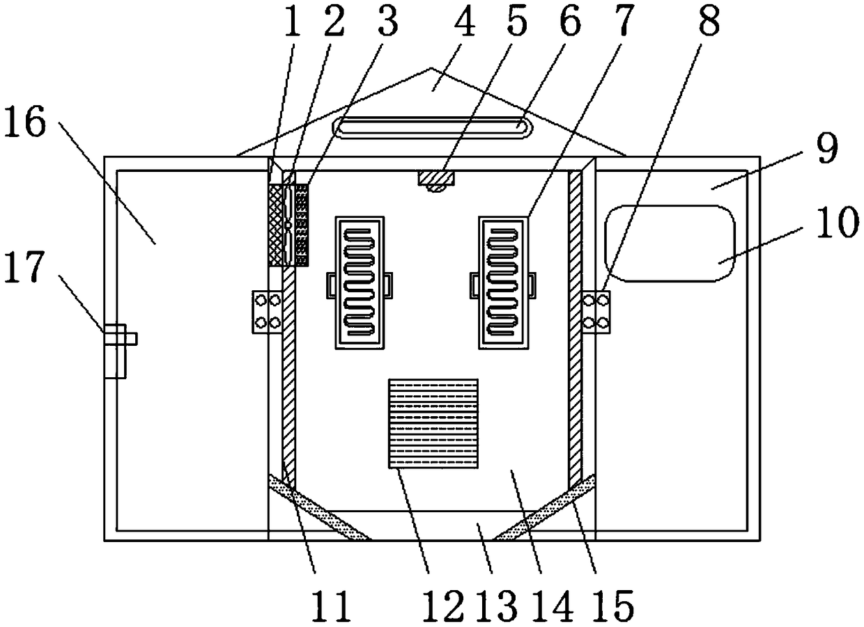
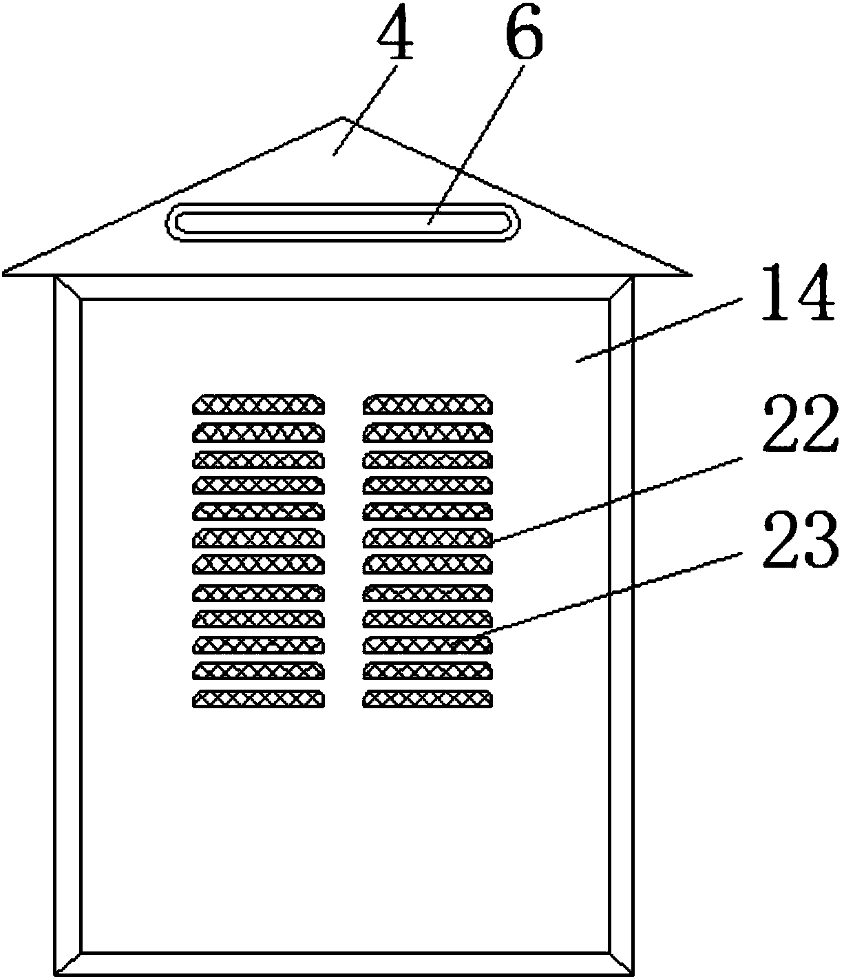
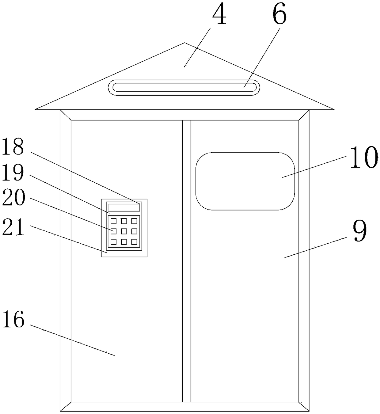
[0023] refer to Figure 1-3 , an outdoor heat dissipation and dustproof power distribution cabinet, comprising a right cabinet door 9, a cabinet body 14, a left cabinet door 16 and a controller outer box 21, a top plate 4 is arranged on the top of the cabinet body 14, and an LED light 6 is arranged on the surface of the top plate 4, A left cabinet door 16 and a right cabinet door 9 are respectively arranged on both sides of the front end of the cabinet body 14, a controller outer box 21 is arranged on the front end of the left cabinet door 16, an observation window 10 is arranged on the front end of the right cabinet door 9, and the top plate 4 The lower surface is p...
PUM
 Abstract
Description
Claims
Application Information