Wireless charging receiving device, wireless charging method and system, and terminal device

A technology of wireless charging and receiving end, which is applied to battery circuit devices, data exchange chargers, collectors, etc., and can solve the problem of low wireless charging efficiency

Inactive Publication Date: 2018-09-14
VIVO MOBILE COMM CO LTD
View PDF7 Cites 15 Cited by
  • Summary
  • Abstract
  • Description
  • Claims
  • Application Information

AI Technical Summary

Problems solved by technology

[0004] Embodiments of the present application provide a wireless charging receiver device, a wireless charging method, system,...

Method used


Image

  • Wireless charging receiving device, wireless charging method and system, and terminal device
  • Wireless charging receiving device, wireless charging method and system, and terminal device
  • Wireless charging receiving device, wireless charging method and system, and terminal device

Examples


Embodiment 1

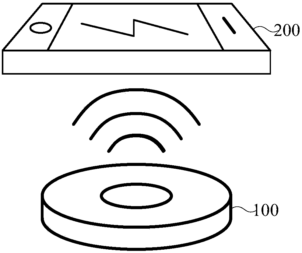
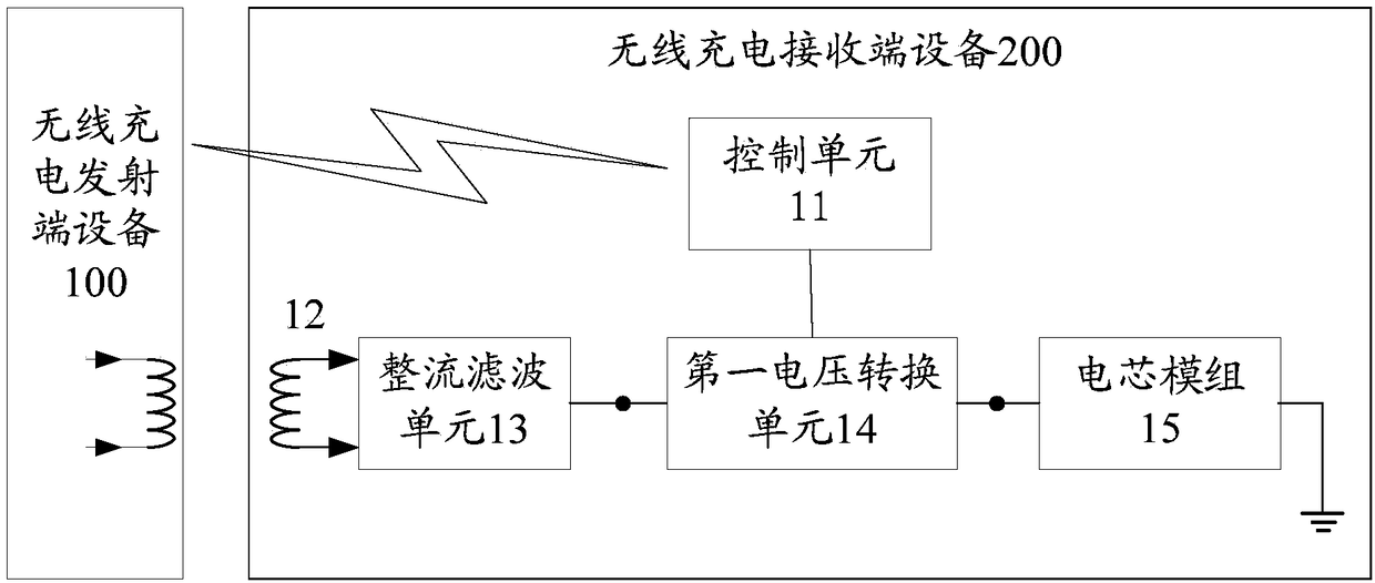
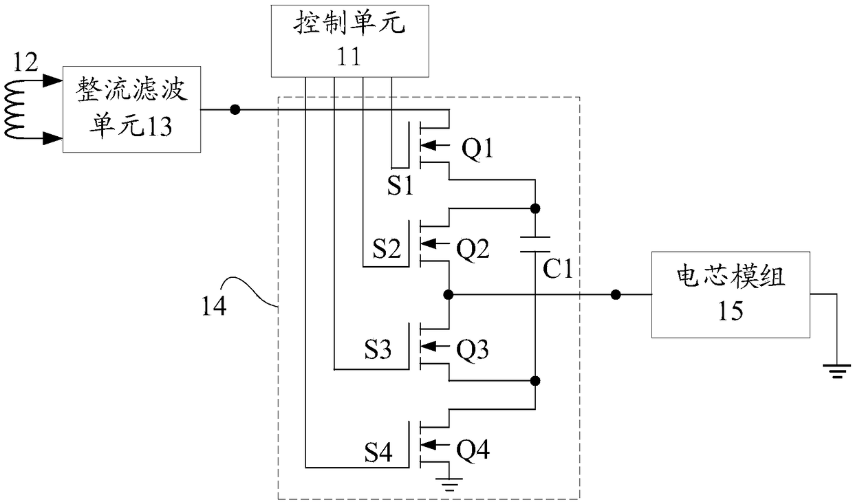
[0043] The embodiment of this application provides a wireless charging receiver device, specifically, refer to figure 2 As shown, the wireless charging receiving device 200 includes: a control unit 11 , a receiving coil 12 , a rectifying and filtering unit 13 , a first voltage converting unit 14 and a battery module 15 .

[0044] The control unit 11 is connected to the first voltage conversion unit 14, for the model of the wireless charging transmitter device 100 belongs to the first preset model set and the output voltage of the battery module 15 is within a preset range In the case of within, sending a first control signal to the wireless charging transmitter device 100 and outputting a second control signal to the first voltage conversion unit 14 .

[0045] Wherein, the first control signal is used to instruct the wireless charging transmitter device 100 to transmit a first electromagnetic wave.

[0046] Optionally, the process for the control unit 11 to realize the above...

Embodiment 2

[0106] An embodiment of the present application provides a wireless charging method, and the execution subject of the wireless charging method may be a wireless charging receiving end device. Specifically, refer to Figure 9 As shown, the method includes:

[0107] S901. Obtain the model number of the wireless charging transmitter device.

[0108] S902. Determine whether the model of the wireless charging transmitter device belongs to the first preset model set.

[0109] In the above step S902, if the model of the wire charging transmitting end device belongs to the first preset model set, step S903 is executed.

[0110] S903. Obtain the output voltage of the battery cell module.

[0111] S904. Determine whether the output voltage of the cell module is within a preset range.

[0112] In step S904 above, if the output voltage of the battery module is within the preset range, step S905 is executed; that is, the model of the wireless charging transmitter device belongs to the ...

Embodiment 3

[0153] Yet another embodiment of the present application provides a terminal device, where the terminal device includes the wireless charging apparatus provided in the foregoing embodiment.

[0154] The terminal device provided in the embodiment of the present application may specifically be a terminal device such as a mobile phone, a tablet computer, a notebook computer, a super mobile personal computer, a netbook, a personal digital assistant, a smart watch, or a smart bracelet, or the terminal device may also be other types of The terminal device is not limited in this embodiment of the application.


PUM


Abstract

The application provides a wireless charging receiving device, a wireless charging method and system, and a terminal device, and relates to the technical field of terminals for reducing energy loss ofa transmitting coil and a receiving coil. The device comprises: a control unit, a receiving coil, a rectifying and filtering unit, a first voltage converting unit and a battery cell module; wherein the control unit is configured to transmit a first control signal to a wireless charging transmitting device and output a second control signal to the first voltage converting unit when the type of thewireless charging transmitting device belongs to a first preset type set and the output voltage of the battery cell module is within a preset range; the receiving coil is configured to sense a firstelectromagnetic wave to generate the first alternating current; the rectifying and filtering unit is configured to convert the first alternating current into the first direct current; the first voltage converting unit is configured to convert the first direct current into second direct current under the control of the second control signal; and the battery cell module is configured to be charged by the second direct current. The wireless charging receiving device is used for wireless charging.

Description

technical field [0001] The present application relates to the field of terminal technology, and in particular to a wireless charging receiver device, a wireless charging method, system, and terminal device. Background technique [0002] Wireless charging technology (Wireless Charging Technology) refers to the charging method in which the charger inputs electric energy into the electric device in a non-contact manner. Since wireless charging technology has many advantages such as avoiding the exposure of the conductive contacts of the charger and the electric device, simplifying the operation of the user when charging, and reducing the wear and tear between the charger and the electric device, the application prospect of the wireless charging technology is very broad. [0003] In general, the process of wireless charging includes: the wireless charging transmitter device converts the electrical energy of the grid power supply into high-frequency alternating current (Alternati...

Claims


Application Information

Patent Timeline
IPC IPC(8): H02J7/02H02J50/10H02J50/70H02J50/80H02J5/00
CPCH02J5/005H02J7/025H02J50/10H02J50/70H02J50/80H02J50/12H02J7/00034H02J50/005
Inventor 魏华兵陈栋
Owner VIVO MOBILE COMM CO LTD
Why Eureka
Try Eureka