
Platform for carrying out numerical-controlled cutting on steel plate based on ships and using method thereof

A technology for steel plates and ships, which is applied in the field of CNC cutting steel plate platforms based on ships, can solve the problem of low precision of cutting steel plates, achieve the effects of high safety and mobility, improve work efficiency, and facilitate operation

Pending Publication Date: 2018-09-18
QINZHOU UNIV
View PDF5 Cites 2 Cited by
  • Summary
  • Abstract
  • Description
  • Claims
  • Application Information

AI Technical Summary

Problems solved by technology

[0003] The invention proposes a platform for cutting steel plates based on ship numerical control and its use method, which solves the problem of low precision in cutting steel plates in the prior art

Method used


Image

  • Platform for carrying out numerical-controlled cutting on steel plate based on ships and using method thereof
  • Platform for carrying out numerical-controlled cutting on steel plate based on ships and using method thereof
  • Platform for carrying out numerical-controlled cutting on steel plate based on ships and using method thereof

Examples


Embodiment 1

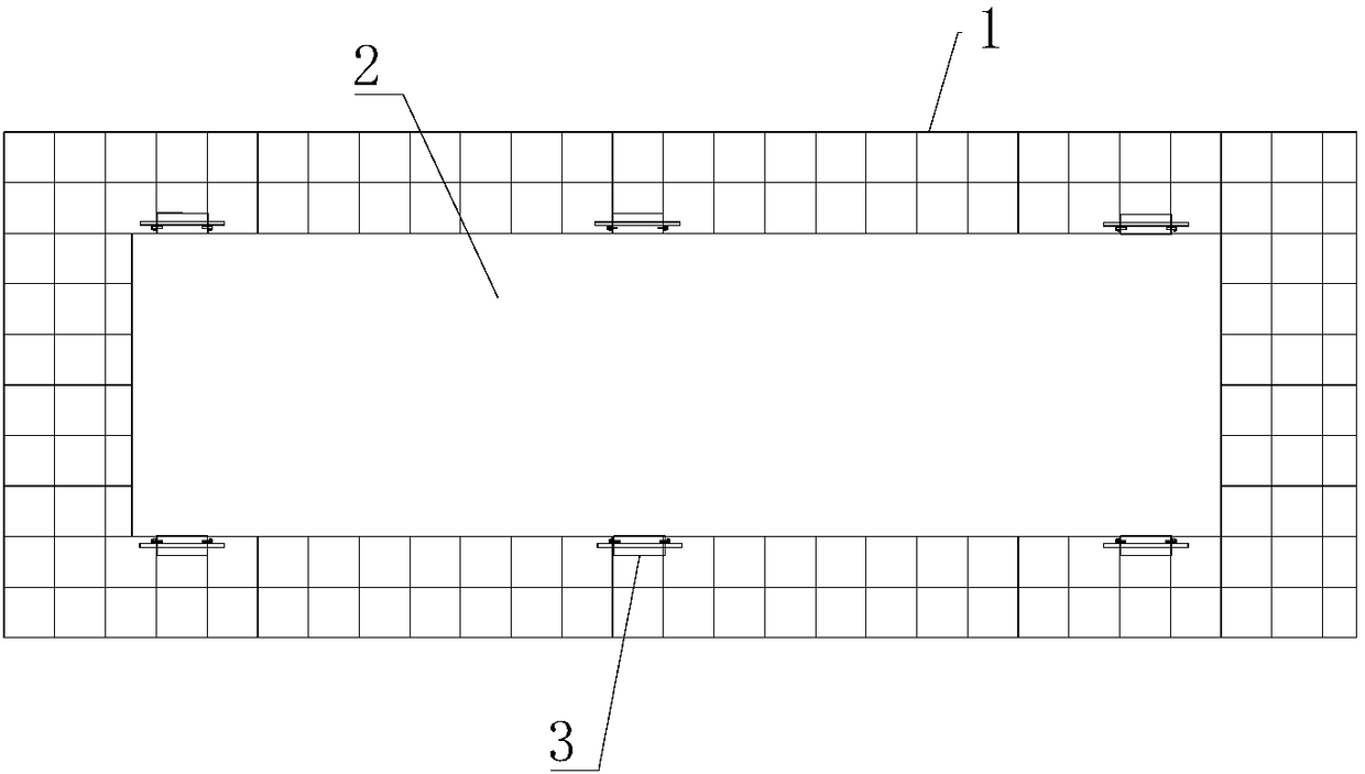
[0036] Such as figure 1 As shown, it is an embodiment of the present invention based on the ship's numerical control cutting steel plate platform. This embodiment includes a tire frame 1 placed horizontally, and a steel plate 2 to be cut is placed on the upper surface of the tire frame 1. The outer surface of the steel plate 2 There are a plurality of auxiliary parts 3 detachably connected with the tire frame 1 at the edge, and the auxiliary parts 3 are symmetrically arranged on the outer circumference of the steel plate 2, and the auxiliary parts 3 fix the steel plate 2 on the On the tire frame 1, when cutting, a numerical control cutting machine (not shown in the figure) walks above the steel plate 2 to cut the steel plate 2. During this process, the auxiliary part 3 can firmly press the steel plate 2 On the tire frame 1, it is ensured that it does not bounce, the cutting accuracy is guaranteed, and peripheral equipment can be protected. The operation is simple, saves time a...

Embodiment 2

[0043] The present invention also proposes a method for using a ship's numerically controlled cutting steel plate platform, including the following sequential steps:

[0044] S1. After the tire frame is assembled and welded, fix it;

[0045] S2. Hoist and lay the steel plate to be cut on the upper surface of the tire frame;

[0046] S3. Use multiple auxiliary parts to fix the steel plate on the upper surface of the tire frame;

[0047] S4. The CNC cutting machine walks and cuts on the steel plate;

[0048]S5. After cutting, remove the auxiliary parts and remove the cut steel plate.

[0049] Wherein, in step S1, the tire frame is welded and fixed by a plurality of criss-cross flat steel; the flat steel is provided with a plurality of through holes for inserting pin shafts at intervals.

[0050] In step S3, the auxiliary part is connected to the tire frame through a pin shaft; the auxiliary part is pressed above the steel plate; and the auxiliary part is arranged symmetricall...


PUM


Abstract

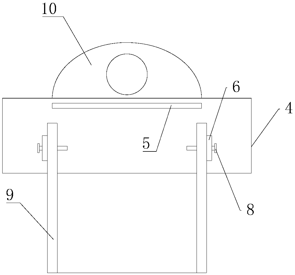
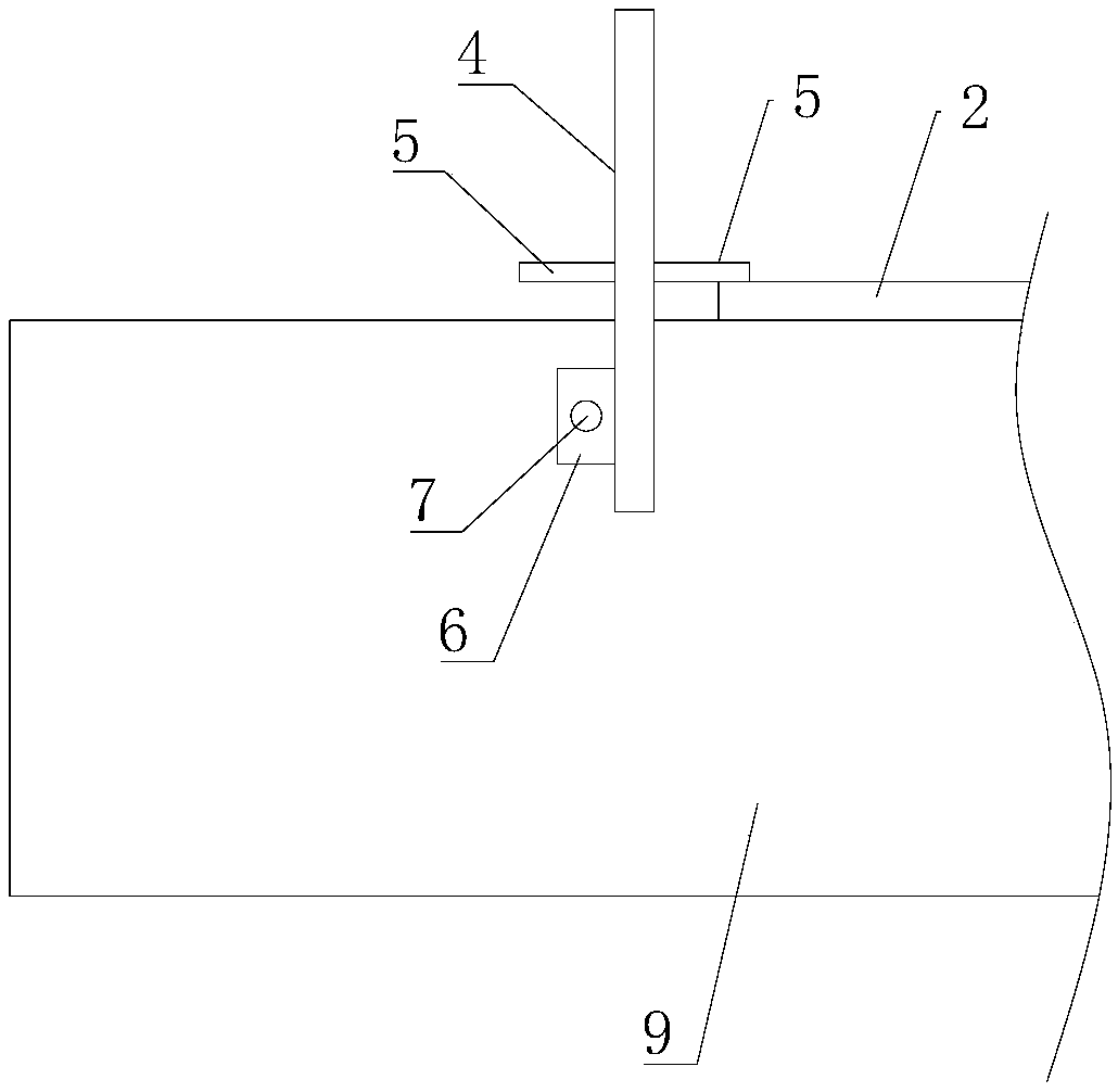
The invention provides a platform for carrying out numerical-controlled cutting on a steel plate based on ships and a using method thereof. The problem that the precision is low when the steel plate is cut in the prior art is solved. The platform comprises an assembly jig which is placed horizontally, wherein a to-be-cut steel plate is placed on the surface of the assembly jig; a plurality of auxiliary parts detachably connected with the assembly jig are arranged on an outer edge of the steel plate; the auxiliary parts are symmetrically arranged at the periphery of the steel plate; the steel plate is fixed to the assembly jig by the auxiliary parts; each of the auxiliary plates comprises a web plate and a face plate, and the web plate and the face plate are perpendicularly and integrally fixed; the web plates are detachably connected with the assembly jig; a plane on which the face plate is located is parallel to a plane on which the steel plate is located; and the face plate is pressed on the edge position of the steel plate and is used for fixing the steel plate to the assembly jig.

Description

technical field [0001] The invention relates to the technical field of ships and ocean engineering equipment, in particular to a ship-based numerical control cutting steel plate platform and a use method thereof with simple structure and convenient use. Background technique [0002] CNC cutting steel plates are widely used in shipbuilding, machinery, chemical industry, construction, and aerospace fields, especially in the rapid development of my country's shipbuilding industry. my country is already a big shipbuilding country. A large number of steel plates are used in the shipbuilding process. Cutting according to the shape of the steel plate designed by the drawing is very Importantly, the precision of steel plate cutting determines the precision control of the ship in the subsequent construction and assembly process. At present, most of the steel plate cutting in the shipyard processing workshop adopts CNC cutting. During the cutting process, the steel plate is not fixed w...

Claims


Application Information

Patent Timeline
Patent Type & Authority Applications(China)
IPC IPC(8): B23Q3/06B23D79/00
CPCB23D79/00B23Q3/062
Inventor 焦自权孙勇敢王侨冯志强焦子硕吕娜夏义江韩鑫张云海黄新欢蔡广华
Owner QINZHOU UNIV
Learn More