
Projectile internal charging structure for preventing flame-over ignition of fuse in explosive-proof state

A fire isolation and fuze technology, which is applied to ammunition, cartridge ammunition, offensive equipment, etc., to solve hidden safety hazards and improve safety

Active Publication Date: 2018-09-18
NANJING UNIV OF SCI & TECH
View PDF1 Cites 2 Cited by
  • Summary
  • Abstract
  • Description
  • Claims
  • Application Information

AI Technical Summary

Problems solved by technology

[0003] The object of the present invention is to provide a charge structure inside the projectile that prevents the fuze from flashing and igniting in the explosion-proof state, so as to solve the problem that the high-temperature and high-pressure gas generated by the accidental ignition of sensitive explosive components such as the detonator inside the fuze is formed through the fuze crack in the explosion-proof state. The potential fire-transfer channel can directly ignite the fire and explosive charge in the projectile body
The fireproof piece of the present invention is specifically applied between the detonator tube of the explosion-proof fuze of the projectile and the charged projectile to solve specific technical problems

Method used


Image

  • Projectile internal charging structure for preventing flame-over ignition of fuse in explosive-proof state
  • Projectile internal charging structure for preventing flame-over ignition of fuse in explosive-proof state
  • Projectile internal charging structure for preventing flame-over ignition of fuse in explosive-proof state

Examples


Embodiment 1

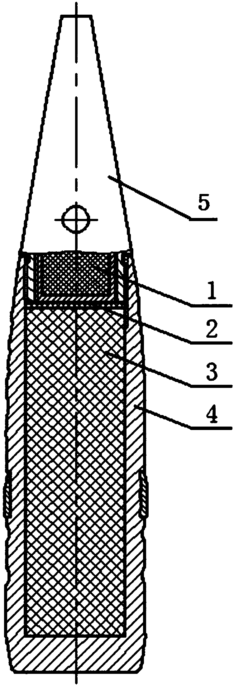
[0019] combine figure 1 , The fire-insulating member 2 of the present invention can be heat-insulating paint or heat-insulating glue (such as GD-433 flame-retardant single-component room temperature vulcanized silicone rubber), and can also be fire-insulating and heat-insulating gaskets such as aluminum foil or tin foil. The heat insulation paint or heat insulation glue or aluminum foil or tin foil and other fire and heat insulation gaskets are directly assembled between the top of the explosive charge 3 and the fuze detonator tube 1 . In addition, the heat-insulating paint or glue and heat-insulating gaskets such as aluminum foil or tin foil should ensure good compatibility with the grain.

Embodiment 2

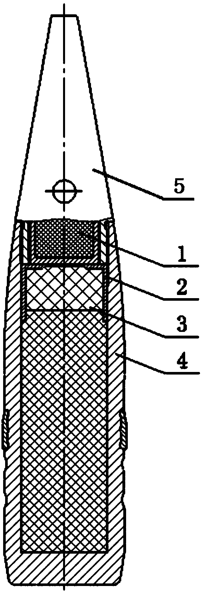
[0021] combine figure 2 , The fire barrier 2 of the present invention is a reinforced cap, and its structural principle is the same as that of the detonator reinforced cap. The reinforcing cap is directly assembled on the top of the propellant charge 3 . The shape of the reinforcing cap changes accordingly according to the shape of the fuze booster tube 1, so as to ensure that its inner surface is in direct contact with the propellant charge 3, and its outer surface is in close contact with the outer contour of the fuze booster tube. The thickness of the middle part of the top layer of the reinforcing cap is thinner than that of the two sides of the top layer. This structure can not only isolate the high-temperature and high-pressure gas leaking through the potential fire transmission path to achieve the purpose of fire isolation, but also does not affect the detonation output of the detonator tube. Completely detonate the projectile or the warhead, and the material of the r...

Embodiment 3

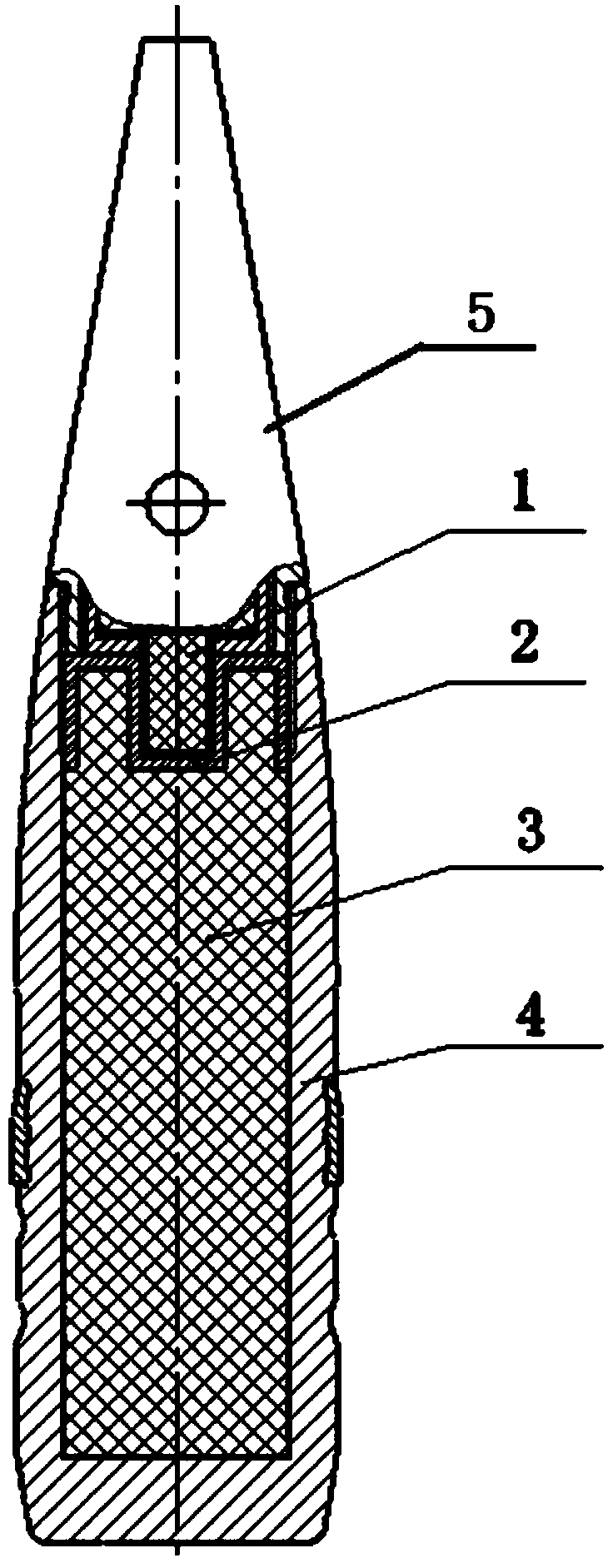
[0023] combine image 3 , the middle part of the fire-proof element 2 is a concave structure, so as to ensure that the inner surface of the fire-proof element is in contact with the main charge of the ammunition, and the outer surface is in close contact with the protruding booster tube of the flameproof fuze.

[0024] The present invention prevents the detonator from accidentally igniting, exploding, and leaking high-temperature and high-pressure gas to accidentally ignite the projectile or the internal fire explosive charge of the warhead. The working process of the charging structure is as follows:

[0025] During service processing and firing in the bore and within the safe distance of the muzzle, if the sensitive explosive element in the flameproof fuze accidentally ignites, since the fuse is not released at this time and is in an explosion-proof state, the high-temperature and high-pressure gas produced by the explosive element will It will not detonate the guide and det...


PUM


Abstract

The invention discloses a projectile internal charging structure for preventing flame-over ignition of a fuse in an explosive-proof state. The projectile internal charging structure comprises an explosive-proof type fuse 5, a flame isolation part 2, propellants and explosives 3 and a charging projectile 4, wherein the explosive-proof type fuse 5 is located on the top of a projectile, the bottom end of the explosive-proof type fuse 5 is provided with a detonating tube 1, and the flame isolation part 2 is arranged between the detonating tube 1 of the explosive-proof type fuse 5 and the chargingprojectile 4 and is in close contact with the detonating tube 1 of the explosive-proof type fuse 5 and the charging projectile 4. The flame isolation part is used for isolating the fuse from leaked high-temperature and high-pressure gas caused by cracking or breaking of structures like a fuse body due to accident ignition of sensitive explosion elements like a detonator inside the fuse in the explosive-proof state, and the situation that the gas flows to the explosive loading surface of the projectile or a battle part to cause combustion and explosion by accident is prevented. The flame isolation part is in close contact with the detonating tube and the explosives in the projectile, and the occupied axial space is very small. By means of the projectile internal charging structure, safety of the projectile or the battle part is improved, and the structure is suitable for small-bore shells, especially small-bore anti-hail cloud-seeding shells with small-size and low-mass fuses.

Description

technical field [0001] The invention belongs to the charge structure technology of projectiles or warheads, and in particular relates to a charge structure inside a projectile which prevents the fuse from escaping and igniting in a flameproof state. Background technique [0002] The "Fuze Environment and Performance Test Method" standard at home and abroad has not clearly stipulated whether the fuze should be installed on the charged projectile during the explosion-proof test, and it has not been clearly stipulated that the fuze body is not allowed to crack during the explosion-proof test of the fuze. , it also allows the fuze body to be opened for adding a firing pin during the explosion-proof test, which leads to the distortion of the explosion-proof safety conclusion, so the detonator in the explosion-proof fuze, especially the sensitive explosive components such as the needle detonator, is accidentally ignited Under certain circumstances, it is possible to generate crack...

Claims


Application Information

Patent Timeline
IPC IPC(8): F42B5/02
CPCF42B5/02
Inventor 王雨时闻泉张志彪
Owner NANJING UNIV OF SCI & TECH
Learn More