Optical system for onboard laser illumination measurement device

An optical system, airborne laser technology, applied in optics, optical components, instruments, etc., can solve the problems of laser light meter ranging, limited irradiation distance, reduced target return light receiving rate, low beam expansion ratio, etc. Achieve the effect of satisfying ranging and irradiation distance, improving receiving efficiency, and increasing ranging and irradiation distance

Pending Publication Date: 2018-09-18
凯迈(洛阳)测控有限公司
View PDF0 Cites 3 Cited by
  • Summary
  • Abstract
  • Description
  • Claims
  • Application Information

AI Technical Summary

Problems solved by technology

The laser emitting unit in the optical system of the airborne laser photometer in the prior art has the problems of low beam expansion magnification and large laser divergence angle, which limits the distance

Method used


Image

  • Optical system for onboard laser illumination measurement device
  • Optical system for onboard laser illumination measurement device
  • Optical system for onboard laser illumination measurement device

Examples


Embodiment Construction

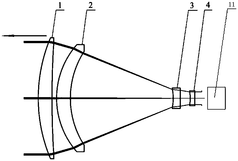
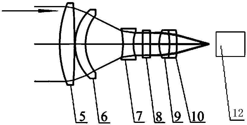
[0029] Such as Figure 1 to Figure 13 As shown, an optical system for an airborne laser illuminator of the present invention includes a laser 11, a collimated beam expander emission unit for collimating and expanding the laser beam emitted by the laser 11 into parallel rays, and an ADP The receiving detector 12 and the receiving unit for focusing the laser light reflected by the target on the photosensitive surface of the ADP receiving detector 12 .

[0030] The collimating beam expanding emitting unit includes a plano-concave negative lens 4, a first double-concave negative lens 3, a second meniscus positive lens 2 and a first meniscus positive lens distributed coaxially along the traveling direction of the laser light emitted by the laser 11. The lens 1, wherein the plane of the plano-concave negative lens 4 is set towards the direction of the laser 11. The light emitted by the laser transmitter passes through the plano-concave negative lens 4 with negative power, the first...


PUM


Abstract

The invention relates to the field of laser guidance equipment and particularly relates to an optical system for an onboard laser illumination measurement device. The optical system comprises a laserdevice, a collimation, beam-expanding and emitting unit, an ADP receiving detector and a receiving unit, wherein the collimation, beam-expanding and emitting unit comprises a plane-concave negative lens, a first double-concave negative lens, a second falcate positive lens and a first falcate positive lens which are sequentially and coaxially distributed along the advancing direction of laser emitted by the laser device, and a plane of the plane-concave negative lens is arranged to face towards the laser device; and the receiving unit comprises a first double-convex positive lens, a third falcate positive lens, a second double-concave negative lens, a 1.064mum interference filter, a second double-convex positive lens and a falcate negative lens which are sequentially and coaxially distributed along the advancing direction of laser received by the ADP receiving detector. The optical system has the advantages of high compression ratio and transmittance and is capable of effectively increasing the ranging distance and illumination distance of the laser illumination measurement device.

Description

technical field [0001] The invention relates to the field of laser guidance equipment, in particular to an optical system for an airborne laser illuminator. Background technique [0002] Laser guidance is an advanced technology that uses target diffuse reflection of laser echo signals with specific codes and wavelengths, forms guidance instructions through receiving devices, and guides guided missiles, artillery shells or bombs to the target to implement precise strikes. Laser guidance technology is a guidance technology commonly used in missiles, bombs and artillery shells at home and abroad. [0003] Accuracy is a distinctive feature of laser-guided weapons. Due to the good monochromaticity of the laser and the small divergence angle of the beam, the laser-guided precision is high and the anti-interference ability is strong. Therefore, when the laser-guided weapon attacks a fixed or moving target, it has a higher target hit rate. Lasers with a high repetition rate can be...

Claims


Application Information

Patent Timeline
IPC IPC(8): G02B27/30G02B27/09G02B1/00G02B19/00
CPCG02B19/0009G02B19/0085G02B27/0927G02B27/0955G02B27/30G02B1/00Y02A90/10
Inventor 吴海清赵新亮李同海谈大伟
Owner 凯迈(洛阳)测控有限公司
Why Eureka
Try Eureka