
Waveguide low-pass harmonic wave suppressor with pits

A harmonic suppressor and waveguide technology, applied in waveguide devices, electrical components, circuits, etc., can solve the problems of filter power capacity reduction, deepening harmonic suppression depth, etc., to achieve deepening suppression depth, widening stopband bandwidth, compact effect

Active Publication Date: 2018-09-18
UNIV OF ELECTRONICS SCI & TECH OF CHINA ZHONGSHAN INST
View PDF8 Cites 2 Cited by
  • Summary
  • Abstract
  • Description
  • Claims
  • Application Information

AI Technical Summary

Problems solved by technology

In order to deepen its harmonic suppression depth and widen its stopband width, it is necessary to reduce the gap between the upper and lower corresponding metal pillars, resulting in a sharp drop in the power capacity of the filter

Method used


Image

  • Waveguide low-pass harmonic wave suppressor with pits
  • Waveguide low-pass harmonic wave suppressor with pits
  • Waveguide low-pass harmonic wave suppressor with pits

Examples


Embodiment 1

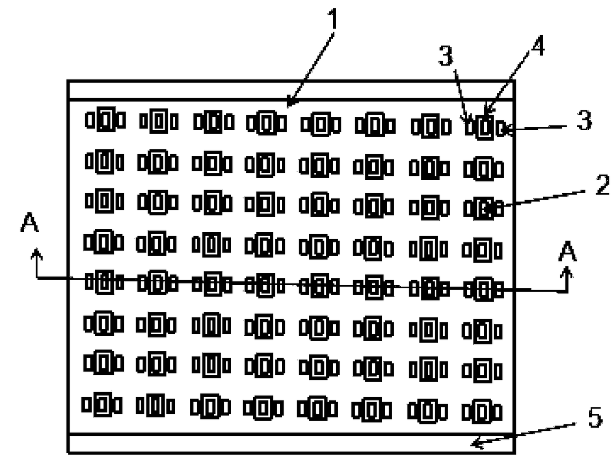
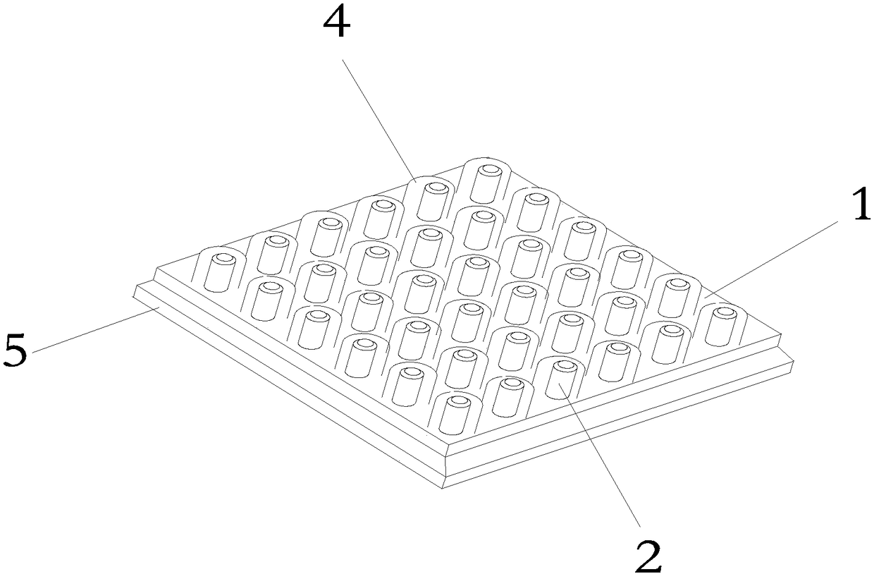
[0017] Such as figure 1 , figure 2 As shown, a waveguide low-pass harmonic suppressor with pits includes a resonant cavity 1, an input and output waveguide 5, and 8 horizontal rows and 8 vertical rows of metal pillars A2 connected to the resonant cavity 1 only at the bottom. The waveguide low-pass harmonic suppressor with pits also includes a metal post B3 corresponding to each metal post A2 and connected to the resonant cavity 1 only at the top; the cross section of the metal post B3 is the same as the cross section of the metal post A2 Sections are different.

[0018] The metal pillars A2 are rectangular, and each metal pillar A2 corresponds to two rectangular metal pillars B3; each metal pillar A2 is embedded between the two corresponding rectangular metal pillars B3. A metal pit 4 is arranged on the top of the resonant cavity 1 corresponding to each of the metal posts A2; each metal post A2 is embedded in the corresponding metal pit 4.

Embodiment 2

[0020] Such as figure 2 As shown, the difference between this implementation example and implementation example 1 is that each of the metal pillars A and each metal pit is a cylinder. No metal post B is provided on top of the cavity.


PUM


Abstract

The invention discloses a waveguide low-pass harmonic wave suppressor with pits. The suppressor comprises a resonance cavity, input and output waveguides and metal columns A. Two rows or over horizontal and two rows or over longitudinal metal columns are provided and only the bottoms are connected with the resonance cavity. The suppressor also comprises metal columns B which correspond to the metal columns A, wherein only the tops of the metal columns B are connected with the resonance cavity. The cross sections of the metal columns B are different from the cross sections of the metal columnsA. Metal pits corresponding to the metal columns A are arranged in the top of the resonance cavity. The metal columns A are embedded into the corresponding metal pits. By use of the above design, under the condition that gaps between the metal columns A and the metal columns B are not reduced and the power capacity of the device is not remarkably reduced, the capacitance between the metal columnsA and the metal columns B is effectively increased, so the stop band inhibition depth of the filter is increased and the stop band bandwidth of the filter is unfolded. The suppressor can be widely applied in radar, missile guidance and all kinds of mobile communication systems.

Description

technical field [0001] The invention relates to a microwave device, in particular to a type of compact high-power harmonic suppression filter. Background technique [0002] Due to the increasing implementation of international and domestic standards for electromagnetic compatibility, harmonic suppression in communication and military electronic systems has increasingly become a key technical issue. The Waffle Iron waveguide low-pass filter has low insertion loss, high power capacity and wide stopband characteristics, and is the main choice for harmonic suppression in high-power communication systems and medium and long-range radars. The traditional Waffle-mode waveguide low-pass filter is composed of vertically symmetrical metal pillar arrays arranged horizontally and vertically. In order to deepen its harmonic suppression depth and widen its stopband width, it is necessary to reduce the gap between the upper and lower corresponding metal pillars, resulting in a sharp drop ...

Claims


Application Information

Patent Timeline
IPC IPC(8): H01P1/212
CPCH01P1/212
Inventor 陈又鲜王清源徐立刘亮元
Owner UNIV OF ELECTRONICS SCI & TECH OF CHINA ZHONGSHAN INST
Learn More