Waste collection device for operating room

A technology for item collection and operating room, which is applied in the field of waste item collection devices for operating rooms, which can solve problems such as troublesome debris cleaning, cleaning personnel scratching hands, and destroying tissue integrity, so as to facilitate cleaning, improve efficiency, and save energy and endurance effects

Active Publication Date: 2018-09-21
王丽娜
View PDF5 Cites 4 Cited by
  • Summary
  • Abstract
  • Description
  • Claims
  • Application Information

AI Technical Summary

Problems solved by technology

[0002] The operating room uses medical instruments such as knives, scissors, and needles to operate on local parts of the human body. It is the main treatment method of surgery. The purpose is to treat or diagnose diseases, such as removing diseased tissues, repairing damage, transplanting organs, and improving the function and shape of the body, etc. , such as cutting, cutting, stitching, abscess drainage, tumor resection, trauma suture, etc., is an operation that destroys the integrity of the tissue, or restores (sutures) the integrity of the damaged tissue. There are a lot of waste items, such as gauze, glass medicine bottles, syringes and other waste items. However, the traditional operating room waste bucket is mostly a big bucket. The waste items during the operation are usually thrown directly into the bucket, which will cause some glass medicines The bottle is directly broken into the bucket, which not only makes the cleaners may scratch their hands during cleaning, but also increases the workload of the cleaners. After the operation is completed, the cleaners will classify and deal with them. It is very troublesome and requires a lot of energy and stamina of the cleaning staff

Method used


Image

  • Waste collection device for operating room
  • Waste collection device for operating room
  • Waste collection device for operating room

Examples


Embodiment Construction

[0026] The following will clearly and completely describe the technical solutions in the embodiments of the present invention with reference to the accompanying drawings in the embodiments of the present invention. Obviously, the described embodiments are only some, not all, embodiments of the present invention. Based on the embodiments of the present invention, all other embodiments obtained by persons of ordinary skill in the art without making creative efforts belong to the protection scope of the present invention.

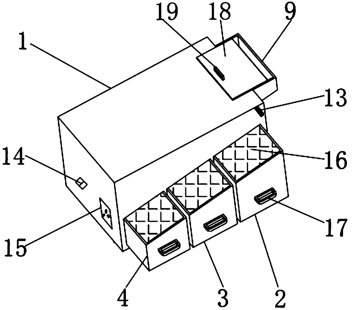
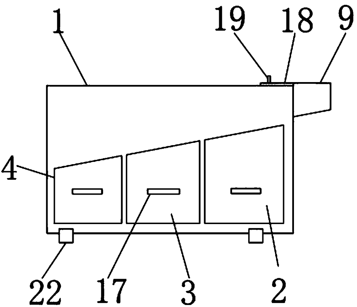
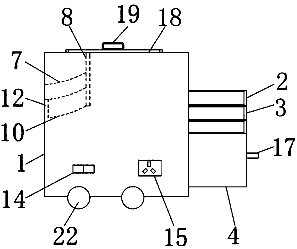
[0027] see Figure 1-5, an embodiment provided by the present invention: a device for collecting waste articles in an operating room, including a housing 1, and the left and right side walls of the interior of the housing 1 are provided with germicidal lamps 13 to sterilize waste articles and prevent them from being cleaned up. To prevent cross-infection of cleaning personnel when discarding articles, and the outer wall of the housing 1 is equipped with a swit...


PUM

PropertyMeasurementUnit
Widthaaaaaaaaaa

Abstract

The invention discloses a waste collection device for an operating room. The waste collection device comprises a shell, the shell is internally provided with a first drawer, a second drawer and a third drawer sequentially from right to left, upper ends of the first drawer and the second drawer are provided with a first slide rail and a second slide rail, the upper end of a fixing plate is fixed tothe inner top end of the shell, and the upper top end of a first retaining plate is fixed to the fixing plate through a torsional spring while the other end of the first retaining plate is closely attached to the side wall of the shell. One end of a second retaining plate is fixed to the fixing plate while an elongated hole is formed between the other end of the second retaining plate and the inner wall of the shell, and the first retaining plate and the second retaining plate are inclined plates. Automatic classified collection of waste articles is realized by quality and shape feature differences of gauze, syringes and glass medicine bottles, and classified treatment performed by cleaning personnel after operation is avoided. The first drawer is internally provided with a partition plate to prevent breakage of the glass medicine bottles in high-speed falling from the first slide rail into the first drawer.

Description

technical field [0001] The invention relates to the field of medical equipment, in particular to a collection device for waste articles used in operating rooms. Background technique [0002] The operating room uses medical instruments such as knives, scissors, and needles to operate on local parts of the human body. It is the main treatment method of surgery. The purpose is to treat or diagnose diseases, such as removing diseased tissues, repairing damage, transplanting organs, and improving the function and shape of the body, etc. , such as cutting, cutting, stitching, abscess drainage, tumor resection, trauma suture, etc., is an operation that destroys the integrity of the tissue, or restores (sutures) the integrity of the damaged tissue. There are a lot of discarded items, such as gauze, glass medicine bottles and syringes, etc. However, the traditional operating room waste bucket is mostly a large bucket, and the waste items during the operation are usually thrown direct...

Claims


Application Information

Patent Timeline
IPC IPC(8): A61B50/37A61M5/32A61L2/10A61L11/00B65F1/00
CPCA61L2/10A61L11/00A61L2202/23A61L2202/26A61M5/3205A61B50/37A61B2050/3008B65F1/004B65F2210/176Y02W30/60
Inventor 关楠
Owner 王丽娜
Why Eureka
Try Eureka