Catalytic reactor suitable for strong exothermic volume reduction

A catalytic reactor and reactor technology, applied in chemical instruments and methods, chemical/physical processes, etc., can solve the problems of large pressure drop, slow removal of reaction heat, and large temperature difference in the catalyst bed, so as to reduce pressure drop and prevent The effect of flying temperature and temperature uniformity

Active Publication Date: 2018-09-21
SHENYANG INSTITUTE OF CHEMICAL TECHNOLOGY
View PDF7 Cites 7 Cited by
  • Summary
  • Abstract
  • Description
  • Claims
  • Application Information

AI Technical Summary

Problems solved by technology

[0005] The purpose of the present invention is to provide a catalytic reactor suitable for strong exothermic volume reduction. The present invention solves the problem of large pressure drop and slow removal of heat of reaction when raw material gas passes through the catalyst bed during the catalytic reaction process of strong exothermic volume reduction. As well as the problem of large temperature difference in the catalyst bed, a radial reactor suitable for catalytic reactions with strong exothermic volume reduction is provided

Method used


Image

  • Catalytic reactor suitable for strong exothermic volume reduction
  • Catalytic reactor suitable for strong exothermic volume reduction

Examples


Embodiment 1

[0027] Embodiment 1 takes the methanation reaction as an example:

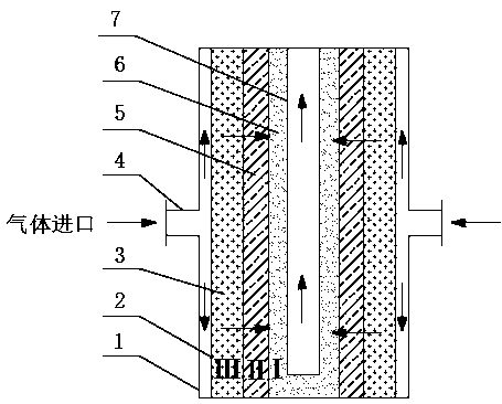
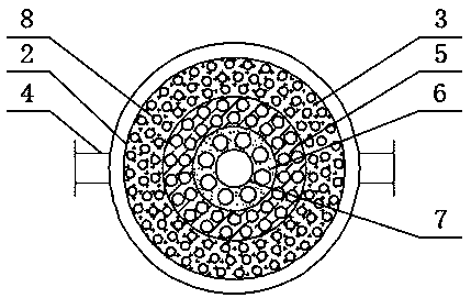
[0028] (1) The catalyst bed can be divided into three areas in the radial direction as an example. The catalysts are packed in the catalyst bed I, II and III in the form of concentric circles, and the catalysts are loaded sequentially with 20Ni / Al 2 o 3 , 10Ni / Al 2 o 3 , 5Ni / Al 2 o 3 .

[0029] (2) Inert gas N 2 It enters the radial reactor from the gas inlet 4, passes through the catalyst bed layers III, II and I in sequence through the gas distribution cylinder 2, enters the inner gas cylinder 7, and is discharged from the gas outlet. Use an inert gas to remove air from the reactor and catalyst bed.

[0030] (3) The reducing gas enters the radial reactor through the air inlet 4, passes through the catalyst bed layer radially through the gas distribution cylinder 2, passes through the catalyst bed layer III, II and I in turn, and reduces the catalyst at a certain temperature, and then The inner gas c...

Embodiment 2

[0032] Embodiment 2 is example with synthetic methanol reaction:

[0033] (1) The catalyst bed is divided into three areas in the radial direction as an example. The catalysts are packed in the catalyst beds I, II and III in the form of concentric circles, and the catalysts CuO / ZnO / Al are loaded in sequence. 2 o 3 、CuO / ZnO / Al 2 o 3 and Al2 o 3 (3:1) and CuO / ZnO / Al 2 o 3 and Al 2 o 3 (1:2).

[0034] (2)H 2 and CO mixture (volume ratio H 2 / CO=2:1) ​​It enters the radial reactor from the gas inlet 4, passes through the catalyst bed layers III, II and I in sequence through the gas distribution cylinder 2 and reacts in the catalyst bed layer. In the catalyst bed III, the amount of reaction gas is relatively large, and the catalyst CuO / ZnO / Al is loaded 2 o 3 and Al 2 o 3 (1:2) mixture, by reducing the amount of catalyst to control the amount of reaction gas to react, thereby reducing the heat of reaction, matching the arrangement of a larger heat exchange area, and pr...


PUM


Abstract

The invention provides a catalytic reactor suitable for strong exothermic volume reduction and relates to a catalytic reactor. The axis of the reactor adopts a U-shaped structure; the U-shaped axis isan inner air cylinder; a catalyst bed layer I (6), a catalyst bed layer II (5), a catalyst bed layer III (3), a gas distribution cylinder (2) and an outer air cylinder (1) are arranged at the periphery of the inner air cylinder (7) symmetrically from inside to outside; a gas inlet (4) is formed in the outer part communicated with the outer air cylinder (1); a heat exchange tube (8) is arranged inthe catalyst bed layer III (3); the reaction raw materials enter the catalyst bed layers along the periphery of the reactor and are discharged from the center of the reactor; the change of the gas volume and the flow channel area is matched; the quantity of reaction occurring at different radial positions is regulated and controlled; gradient filling of the catalyst is matched; heat of the tube bundles in the catalyst bed layers is transferred gradiently; and bed layer reaction heat balancing and heat exchange tube bundle heat transfer are completed. The reactor is particularly suitable for places of strong exothermic volume reduction reaction to realize uniformization of bed layer gas flow speed and bed layer temperature.

Description

technical field [0001] The invention relates to a catalytic reactor, in particular to a catalytic reactor suitable for volume reduction of strong heat release. Background technique [0002] Fixed-bed reactors are widely used in gas-solid phase catalytic reactions in the chemical industry. For reactions with strong exothermic and volume reduction such as Fischer-Tropsch synthesis, ammonia synthesis, methanation, etc., traditional fixed-bed reactors have limited transfer Thermal properties lead to a certain temperature difference between the axis and the radial direction of the catalyst bed, which in turn leads to the formation of local hot spots in the catalyst bed or the overheating of the catalyst bed, causing catalyst sintering and even deactivation. In addition, the traditional fixed-bed reaction design also has the disadvantage of large pressure drop when the reactant gas passes through the catalyst bed. [0003] In the industrial tube-and-tube reactor, the catalyst is ...

Claims


Application Information

Patent Timeline
Patent Type & Authority Applications(China)
IPC IPC(8): B01J8/02B01J8/04
CPCB01J8/0214B01J8/0285B01J8/0411B01J2208/00132
Inventor 许光文石磊韩振南李盼盼
Owner SHENYANG INSTITUTE OF CHEMICAL TECHNOLOGY
Why Eureka
Try Eureka