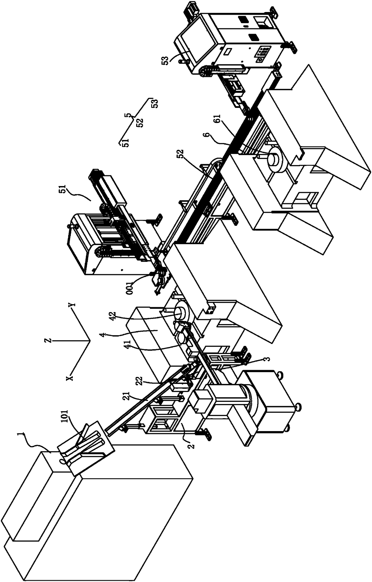
Full-automatic ball cage forging production line
A fully automatic, production line technology, applied in the direction of manufacturing tools, metal processing equipment, forging presses, etc., can solve the problems of the complex structure of the ball cage processing production line, the temperature drop of the ball cage embryo material, and the low efficiency of transplanting and feeding, and achieve the goal of transplanting The effect of fast speed, reasonable layout and small footprint
- Summary
- Abstract
- Description
- Claims
- Application Information
AI Technical Summary
Problems solved by technology
Method used
Image

Examples
Embodiment Construction
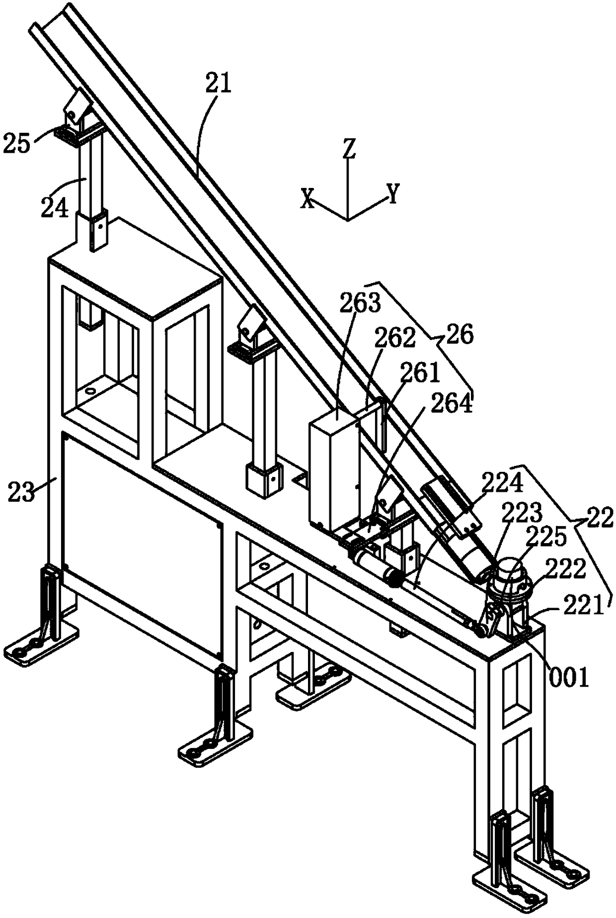
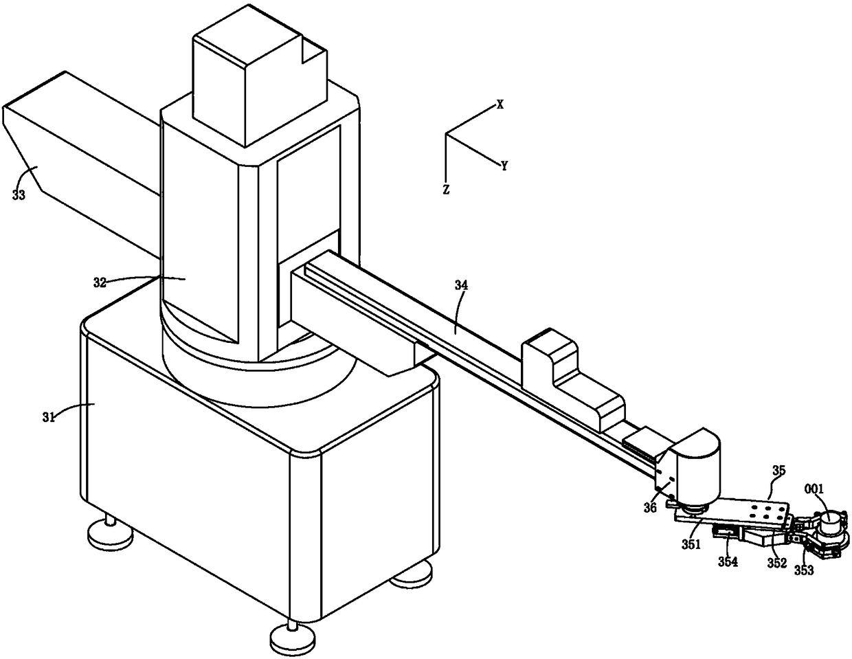
[0030] The present invention will be described in further detail below in conjunction with the accompanying drawings.
[0031]The embodiments described by referring to the figures are exemplary and are intended to explain the present application and should not be construed as limiting the present application. In the description of the present application, it should be understood that the terms "center", "longitudinal", "transverse", "length", "width", "thickness", "upper", "lower", "front", " Orientation or position indicated by "back", "left", "right", "vertical", "horizontal", "top", "bottom", "inner", "outer", "clockwise", "counterclockwise", etc. The relationship is based on the orientation or positional relationship shown in the drawings, and is only for the convenience of describing the present application and simplifying the description, rather than indicating or implying that the referred device or element must have a specific orientation, be constructed and operated i...
PUM
 Abstract
Description
Claims
Application Information