
Circular steel tube welding machine

A technology of round steel pipes and welding machines, which is applied in the direction of welding equipment, auxiliary welding equipment, welding/cutting auxiliary equipment, etc., can solve the problems of difficult round steel pipes in synchronous motion state, affecting the reliability of welding joints, and unreliable welding joints, etc., to achieve Simple and convenient adjustment, improved welding efficiency and strong practicability

Active Publication Date: 2018-09-21
如东道博智能设备有限公司
View PDF5 Cites 11 Cited by
  • Summary
  • Abstract
  • Description
  • Claims
  • Application Information

AI Technical Summary

Problems solved by technology

However, since the two steel pipes are disconnected at the beginning, in the process of welding, it is easy to cause the disadvantage of unreliable welding by rotating the round steel pipe. The main reason is that it is difficult to ensure that the two round steel pipes are in the absolute The synchronous motion state of the two round steel pipes, so that when the rotation speed of the two round steel pipes deviates slightly, it will cause the misalignment of the originally aligned steel pipes, which will affect the reliability of the weld

Method used


Image

  • Circular steel tube welding machine
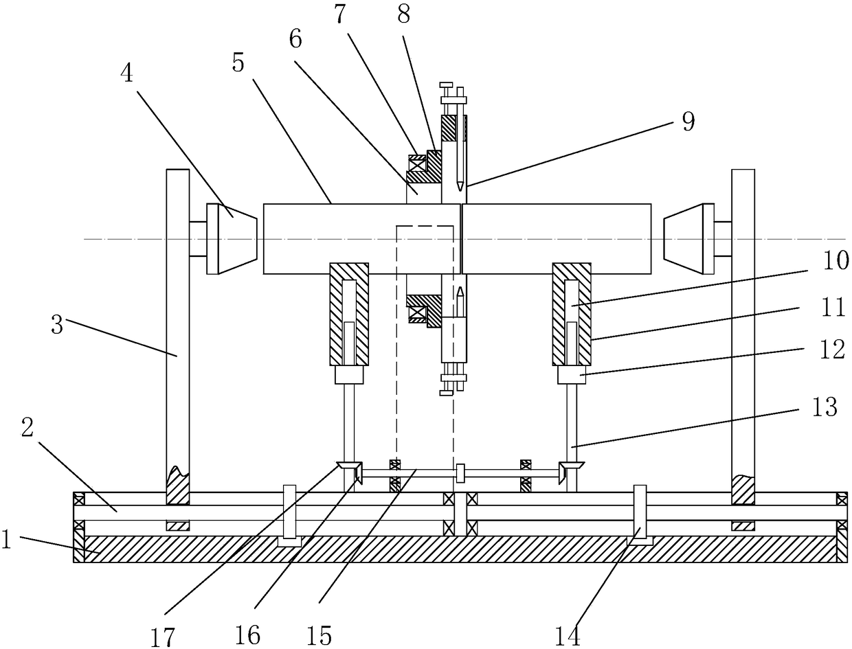
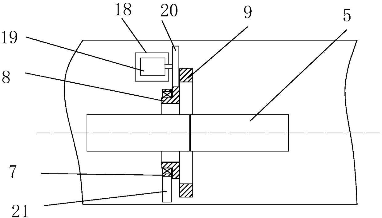
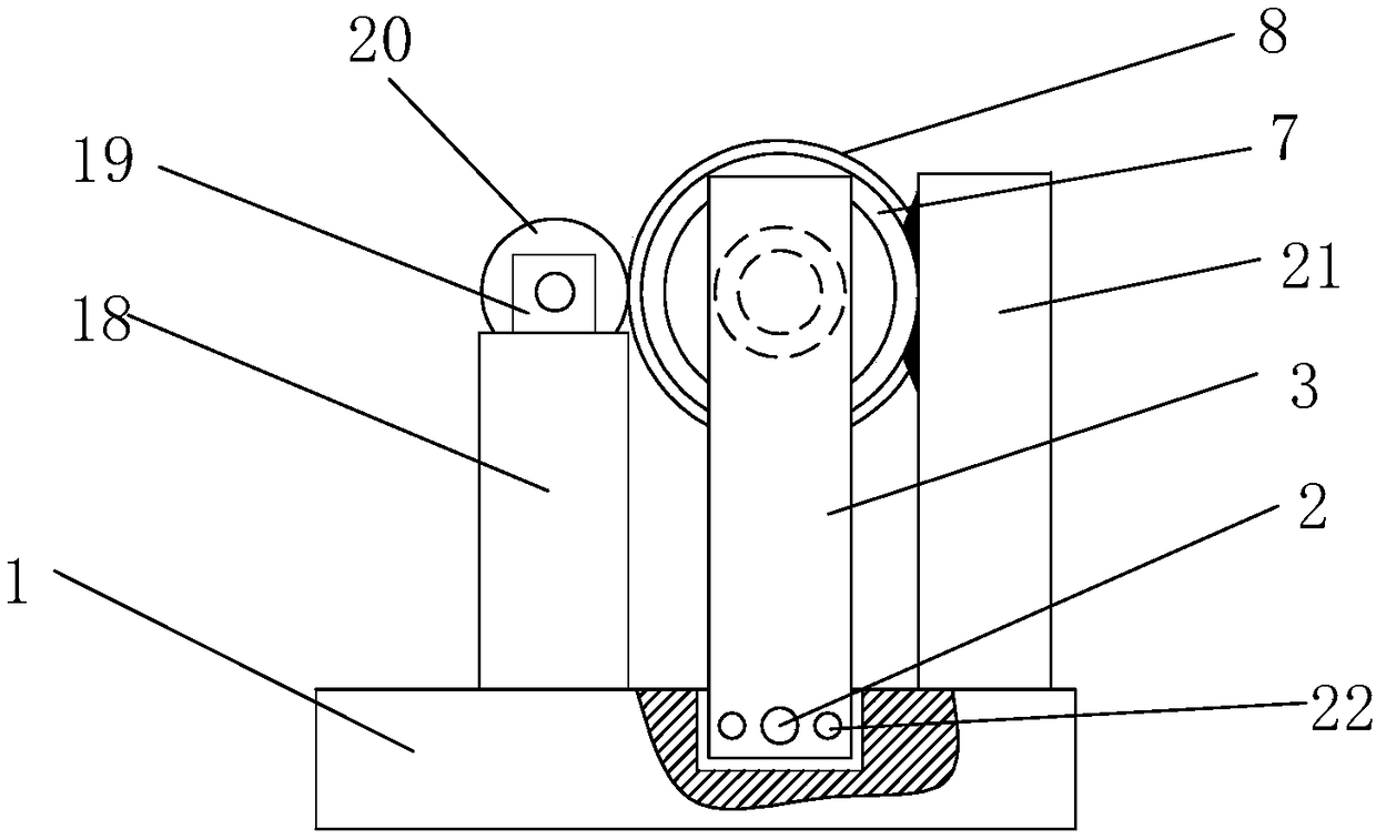
  • Circular steel tube welding machine
  • Circular steel tube welding machine

Examples


Embodiment Construction

[0021] The present invention will be further described in conjunction with the accompanying drawings and specific embodiments. It should be understood that these examples are only used to illustrate the present invention and are not intended to limit the scope of the present invention. In addition, it should be understood that after reading the content taught by the present invention, those skilled in the art may make various changes or modifications to the present invention, and these equivalent forms also fall within the scope defined in the present application.

[0022] Such as Figure 1~5 As described above, a round steel pipe welding machine includes a base 1 on which a support mechanism, a tightening mechanism and a welding mechanism are arranged. The support mechanism includes two support seats 11, and a support drive assembly is arranged under the support seats 11. Two The support base 11 can be lifted vertically under the control of the support drive assembly. The ja...


PUM


Abstract

The invention provides a circular steel tube welding machine. The circular steel tube welding machine comprises a supporting mechanism, a jacking mechanism and a welding mechanism. The supporting mechanism comprises two supporting bases, a supporting drive assembly is arranged below the supporting bases, and the two supporting bases can vertically rise and fall under control of the supporting drive assembly. The jacking mechanism comprises two edge movable plates, a thimble is mounted on the inner side face of each edge movable plate, and two sets of jacking drive assemblies are arranged on abase and used for controlling the two edge movable plates to synchronously and reversely move in the horizontal direction. The welding mechanism comprises a supporting disc, a drive disc and a weldinggun disc. One side of the drive disc is rotationally mounted in the supporting disc, and the other side of the drive disc is fixedly connected with the welding gun disc. According to the welding machine, circular steel tubes are welded by rotating a welding gun, the efficiency is high, as the circular steel tubes are static in the welding process, the circular steel tubes are firm and stable after being welded, and the strength of the positions of weld joints is high.

Description

technical field [0001] The invention mainly relates to the technical field of mechanical equipment, in particular to a round steel pipe welding machine. Background technique [0002] The welding of round steel pipes is to connect two sections of steel pipes by welding. The general welding method is to fix the two sections of round steel pipes butt joints, and then weld them by means of automatic welding machines or manual welding torches. Wherein, in the process of utilizing an automatic welding machine or a manual welding torch to weld, the welding of one week is generally realized by rotating a round steel pipe. However, since the two steel pipes are disconnected at the beginning, in the process of welding, it is easy to cause the disadvantage of unreliable welding by rotating the round steel pipe. The main reason is that it is difficult to ensure that the two round steel pipes are in absolute The synchronous motion state of the two circular steel pipes, so that when the ...

Claims


Application Information

Patent Timeline
IPC IPC(8): B23K37/053B23K37/02
CPCB23K37/02B23K37/053B23K37/0531
Inventor 李红雨
Owner 如东道博智能设备有限公司
Learn More