Paper cutter set with adjustable width

A paper-cutting and machine-knife technology, applied in the field of paper-cutting equipment, can solve the problems of time-consuming, labor-intensive, and unstable precision of knives

Pending Publication Date: 2018-09-21
SHAANXI UNIV OF SCI & TECH
View PDF0 Cites 4 Cited by
  • Summary
  • Abstract
  • Description
  • Claims
  • Application Information

AI Technical Summary

Problems solved by technology

[0003] In order to solve the above-mentioned time-consuming and labor-intensive problems of manual movement and knife setting, and unstable precision, the present invention provides a paper cutter knife set with adjustable width, which can automatically collect position information, and move the cutting knife to adjust the width At the same time, it is more convenient to collect the displacement of the tool in real time during the tool setting

Method used


Image

  • Paper cutter set with adjustable width
  • Paper cutter set with adjustable width
  • Paper cutter set with adjustable width

Examples


no. 1 example

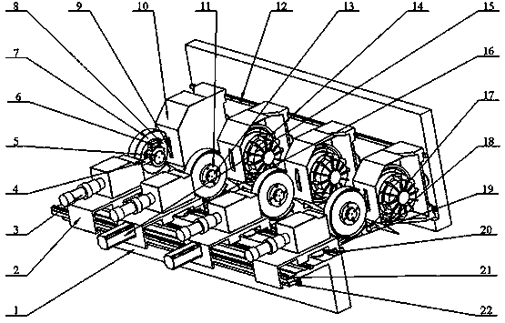
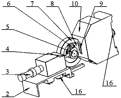
[0070] refer to Figure 7 , in the first embodiment, the cutter group of the paper cutter includes a five-component cutter group, which is divided into the first, second, third, third, and fifth slitting knife groups from right to left, and the first slitting knife group The second, third, fourth, and fifth slitting knife groups all use amplitude-modulated slitting knife groups. The first slitting knife group is not equipped with X-axis precise displacement devices for the workbench. , the rest of the structure is the same as the amplitude modulation cutting knife group.

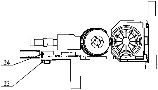
[0071] In this embodiment, the openable and closable connection device is adopted as a group of connection devices connected to the docking base 19 through the docking cylinder rod 17 of the docking cylinder 18; the docking cylinder 18 and the docking base 19 are respectively installed on On the two cutter assemblies of the cutter group; the docking cylinder 18 can be installed on the active knife shell 10,...

no. 2 example

[0092] refer to figure 1 , Figure 8 , as a variant of the present invention, the second embodiment divides the slitting knife group into the first slitting knife group, the second slitting knife group, the third slitting knife group, and the fourth slitting knife group; wherein, The first and fourth slitting knife groups are fixed slitting knife groups, and the second and third slitting knife groups are amplitude-modulated slitting knife groups.

[0093] The first slitting knife group is fixedly installed at the beginning of the grating ruler 22; the first slitting knife group does not have a grating reading head 23; the displacement of the driven knife face of the first slitting knife group relative to the laser sensor measuring point is S 1 ;The X-axis width from the laser sensor measurement point of the first slitter group to the zero point of the grating ruler is L 1 , L 1 is a fixed width;

[0094] The second slitting knife group is an amplitude modulation slitting k...


PUM


Abstract

The invention relates to a paper cutter set with adjustable width. The paper cutter set with adjustable width mainly comprises a base, a cutting knife (including a driven cutter assembly body and an active cutter assembly) and a control system. A fixed cutting knife is arranged at two ends of the base, respectively, the trimming operation is carried out, the width adjustment is achieved through the movement of two identical dividing cutters in the middle, a grating reading head is fixed on the working table of the middle moving dividing cutter, and the movement displacement is detected, and iscontrolled by a control system; when the cutter is required to be subjected to abrasion, the micro-displacement of the cutter is detected by the sensor arranged on the side of the moving blade, and the cutter position data stored in the correction system is compensated to the control system, so that the tool bit is accurate. By the action of the paper cutter set with adjustable width, the aim ofautomatically detecting the displacement, adjusting the width and finally freeing the manpower can be achieved.

Description

technical field [0001] The invention relates to a paper cutting device, in particular to a paper cutter knife set with adjustable width. Background technique [0002] In the prior art, there are usually multiple slitting knives arranged opposite to each other on the paper cutter. During the production process, the distance between the slitting knives needs to be adjusted according to the width of the paper to be produced. And the slitting knife of the paper cutter is generally slidably arranged on the slide rail, and when adjusted to the desired position, it is fixed by a fastener. When adjusting the slitting knife, it needs to be adjusted manually, and sometimes it needs to be adjusted repeatedly, which is time-consuming and laborious, and the accuracy is relatively unstable. Contents of the invention [0003] In order to solve the above-mentioned time-consuming and labor-intensive problems of manual movement and knife setting, and unstable precision, the present invent...

Claims


Application Information

Patent Timeline
Patent Type & Authority Applications(China)
IPC IPC(8): B26D7/26G01B11/02
CPCB26D7/2635G01B11/02
Inventor 郑甲红霍启新赵佳龙谢瀚森李均毛廷廷王亚雄陈静
Owner SHAANXI UNIV OF SCI & TECH
Why Eureka
Try Eureka