Spiral feeding machine

A spiral feeding and spiral conveying technology, applied in the direction of coating, etc., can solve the problems of small vibration amplitude, high labor intensity, low work efficiency, etc., and achieve the effect of small footprint, long conveying stroke and compact structure

Pending Publication Date: 2018-09-21
江苏宇乐机械设备有限公司
View PDF0 Cites 0 Cited by
  • Summary
  • Abstract
  • Description
  • Claims
  • Application Information

AI Technical Summary

Problems solved by technology

At present, in the existing production line, the process of conveying rubber particles to the casting machine is usually operated by lifting platform to assist manual dumping, but this method has low work efficiency and high labor intensity, and the safety factor is not high. Poor, the vibration amplitude of one motor is not large, and the work efficiency is poor

Method used


Image

  • Spiral feeding machine

Examples


Embodiment Construction

[0016] The following will clearly and completely describe the technical solutions in the embodiments of the present invention with reference to the accompanying drawings in the embodiments of the present invention. Obviously, the described embodiments are only some, not all, embodiments of the present invention. Based on the embodiments of the present invention, all other embodiments obtained by persons of ordinary skill in the art without making creative efforts belong to the protection scope of the present invention.

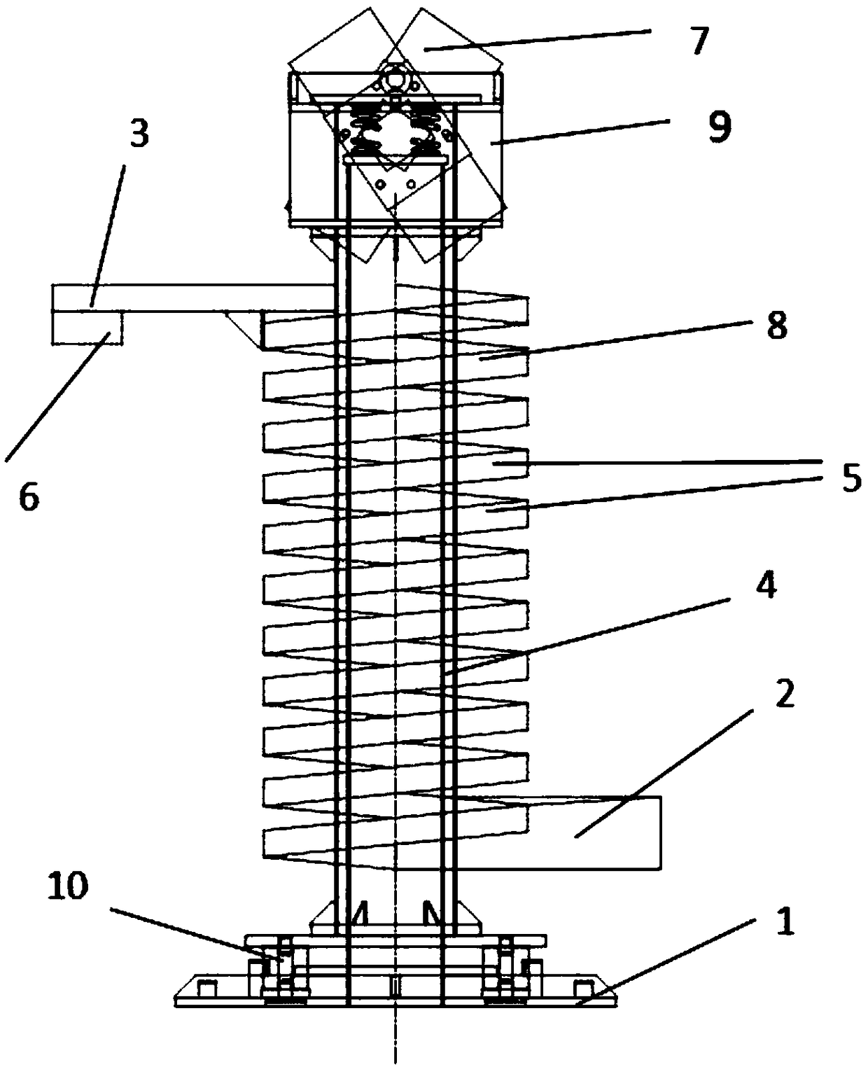
[0017] Such as figure 1 As shown, a screw feeder according to the present invention is composed of a base 1, a material inlet 2, a discharge device 3, a column 4, a spiral conveying groove 5 and a vibrating motor 7, and a Column 4, the column 4 is continuously stress-free welded with the spiral conveying groove 5, the bottom of one side of the spiral conveying groove 5 is provided with a material inlet 2, and the upper part of the other side of the spiral conv...


PUM


Abstract

The invention relates to a spiral feeding machine. The spiral feeding machine is composed of a base, a feeding inlet, a discharging device, an upright column, a spiral conveying trough and a vibrationmotor. The spiral feeding machine is characterized in that the upright column is installed on the upper portion of the base, the upright column is in continuous unstressed welding connection with thespiral conveying trough, the feeding inlet is formed in the bottom on one side of the spiral conveying trough, the discharging device is arranged on the upper portion on the other side of the spiralconveying trough, and a discharging outlet is formed in the discharging device; the vibration motor is installed on the top of the upright column, the spiral conveying trough is composed of a plurality of molding material trays, a vibration motor installation base is arranged on the periphery of the vibration motor, and the base is further provided with rubber springs. The spiral feeding machine has the advantages that the occupied area is small, the structure is compact, the feeding speed is high, labor is saved, and the feeding machine is safe and reliable.

Description

technical field [0001] The invention relates to the technical field of mechanical equipment, in particular to a screw feeder. Background technique [0002] The screw feeder is a supporting auxiliary machine required by plastic processing machinery. It can directly and automatically transport clean powdery or granular plastic raw materials into the hopper. It is a special equipment for adjusting the mixer. At present, in the existing production line, the process of conveying rubber particles to the casting machine is usually operated by lifting platform to assist manual dumping, but this method has low work efficiency and high labor intensity, and the safety factor is not high. Poor, the amplitude of vibration of a motor is not large, and the working efficiency is poor. Therefore, it is necessary to design a feeding machine that has a good cooling effect, is completely free from contamination during the conveying process, does not bring in any foreign matter, and can automat...

Claims


Application Information

Patent Timeline
Patent Type & Authority Applications(China)
IPC IPC(8): B29C31/04B29C41/34
CPCB29C31/04B29C41/34
Inventor 陈羽张艳顾新萍
Owner 江苏宇乐机械设备有限公司
Why Eureka
Try Eureka