Air pressure corner pantograph and monitoring system and monitoring method

A technology of pantograph and corner, which is applied in collectors, electric vehicles, power collectors, etc. It can solve the problems of large investment and a large number of detection points, and achieve the effects of simple control method, avoiding accidents, and simple structure

Active Publication Date: 2018-09-21
山东省阳信铭泰电气有限公司
View PDF10 Cites 2 Cited by
  • Summary
  • Abstract
  • Description
  • Claims
  • Application Information

AI Technical Summary

Problems solved by technology

The above measurement devices are installed on a fixed elevated frame. Since the wear of the pantograph is mainly related to factors such as the speed of the vehicle and the smoothness of the catenary, the wear conditions are not nearly the same in each mileage section of the locomotive. To maintain the catenary according to the we

Method used


Image

  • Air pressure corner pantograph and monitoring system and monitoring method
  • Air pressure corner pantograph and monitoring system and monitoring method
  • Air pressure corner pantograph and monitoring system and monitoring method

Examples


Embodiment Construction

[0034] The following will clearly and completely describe the technical solutions in the embodiments of the present invention with reference to the accompanying drawings in the embodiments of the present invention. Obviously, the described embodiments are only some, not all, embodiments of the present invention. Based on the embodiments of the present invention, all other embodiments obtained by persons of ordinary skill in the art without creative efforts fall within the protection scope of the present invention.

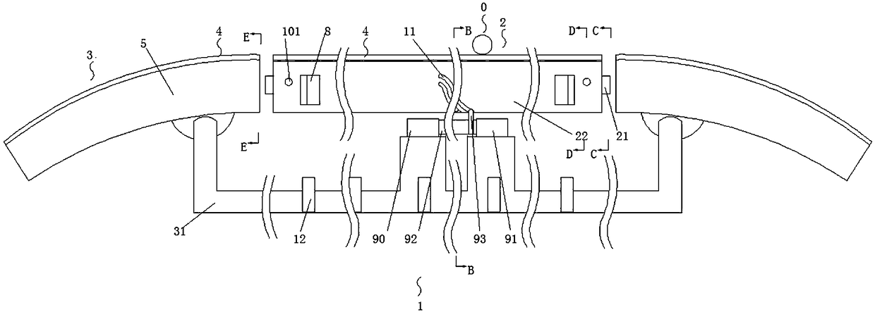
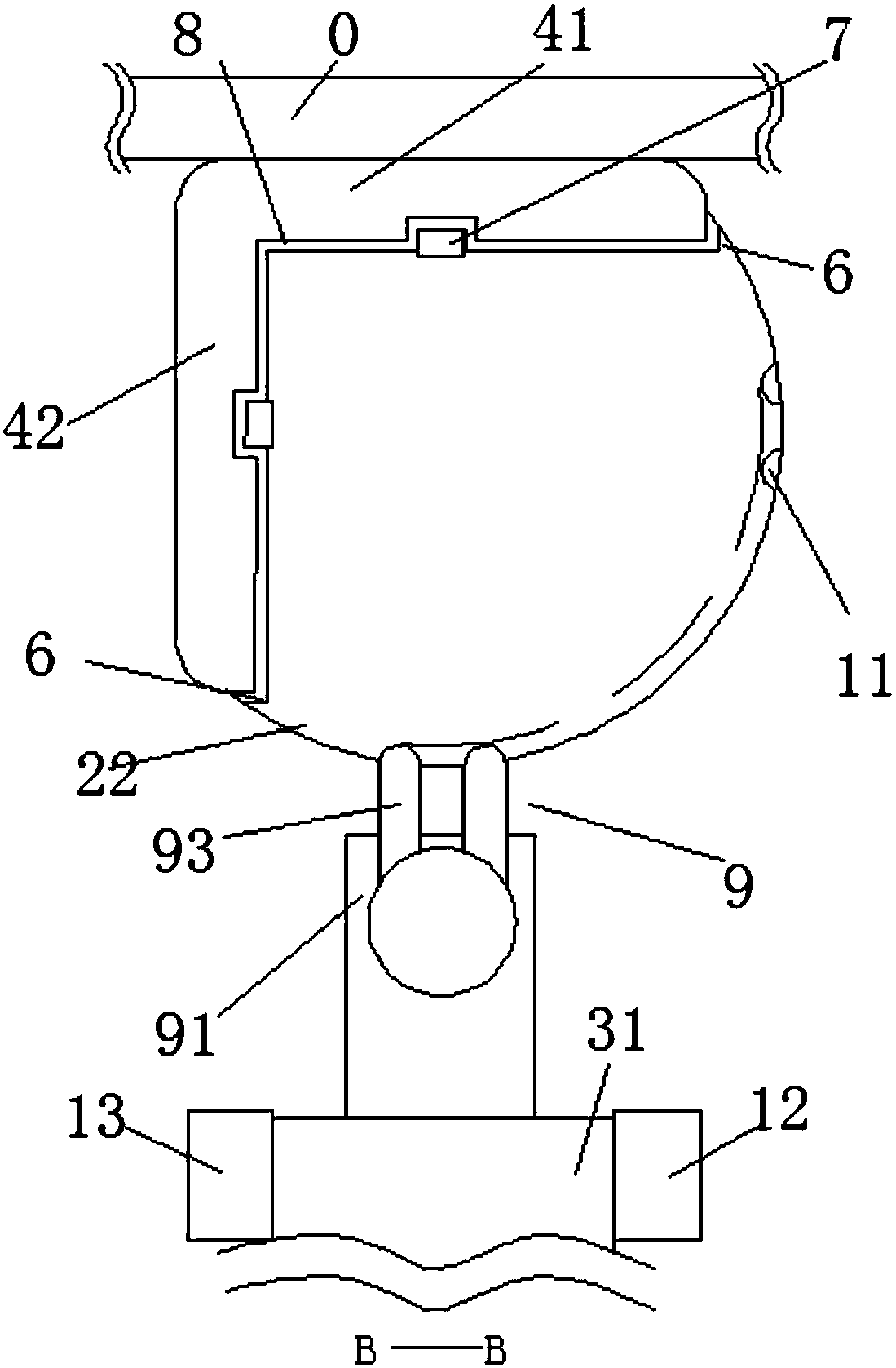
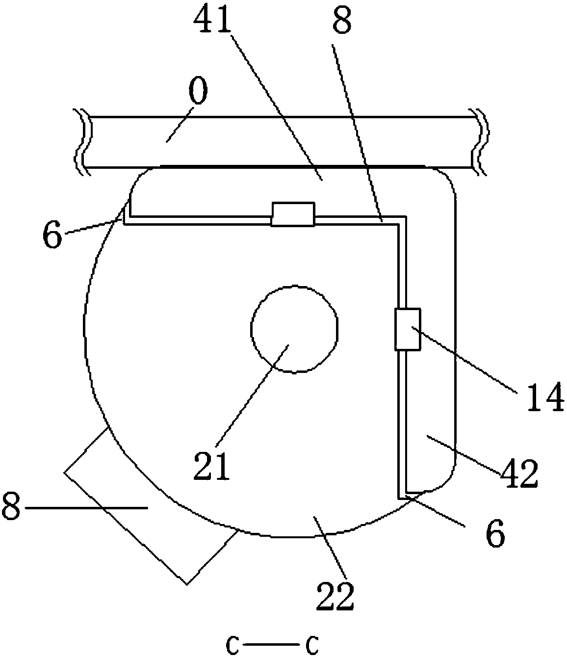
[0035] An air pressure angle pantograph and its monitoring system, such as figure 1It is a top view of a working state of the pantograph 1, including the action section 2 of the pantograph 1 in the middle and the arc sections 3 on both sides. The arc section 3 is installed on the bracket 31, and the action section 2 extends through the center of both ends The rotating shaft 21 is rotatably connected with the arc section 3, the upper part of the action section 2 is ...


PUM


Abstract

The invention provides an air pressure corner pantograph and a monitoring system and a monitoring method. The air pressure corner pantograph.is characterized in that the cross section of the bow is fan shaped. At least two concave guide rails are arranged on the curved surface of the bow body. The steering of the pantograph carbon slide is realized by converting the linear movement of the guide column into the rotation of the bow body. The marginal image of the carbon slider is collected through the fiber optic sights on both sides of the pantograph bracket. Then the marginal image of the carbon slider merged into the whole is matched for the driver to judge the wear of the pantograph, and perform the rotating carbon skateboard or bow down operation.

Description

technical field [0001] The present invention relates to the technical field of pantographs for electric locomotives and EMUs, in particular to an air-compressed corner pantograph, an air-pressure corner pantograph monitoring system, and an air-pressure corner pantograph bow monitoring method. Background technique [0002] During the operation of locomotives or EMUs, the pantograph slides are constantly impacted and vibrated frequently by the catenary. When the slide plate is broken, under the condition of being continuously impacted and vibrated by the catenary, the strength of the broken part is greatly reduced, and the edge is easily broken and falls off to form a groove. When the locomotive or EMU is turning, the catenary is easily stuck, causing damage to the bow and net, and even serious safety accidents. In order to avoid pantograph-catenary accidents, the sliding plate of the pantograph must be checked frequently. Once the pantograph is excessively worn, the bow sho...

Claims


Application Information

Patent Timeline
IPC IPC(8): B60L5/20B60L5/32
CPCB60L5/205B60L5/32
Inventor 许燕兵彭耐
Owner 山东省阳信铭泰电气有限公司
Why Eureka
Try Eureka