Multi-functional unmanned aerial vehicle

A kind of unmanned aerial vehicle and multi-functional technology, applied in the field of unmanned aerial vehicles, can solve the problems such as the difficulty of adjusting the center of gravity, and achieve the effect of improving connection stability, reducing resistance and increasing stability

Active Publication Date: 2018-09-21
河南省豫石地质勘查技术有限公司
View PDF8 Cites 3 Cited by
  • Summary
  • Abstract
  • Description
  • Claims
  • Application Information

AI Technical Summary

Problems solved by technology

This structure judges in real time whether the center of gravity is appropriate through the frequency of the corresponding buzzer, but for equipment with heavy loads, it is difficult to adjust the center of gravity only by means of sliders

Method used


Image

  • Multi-functional unmanned aerial vehicle
  • Multi-functional unmanned aerial vehicle
  • Multi-functional unmanned aerial vehicle

Examples


Embodiment 1

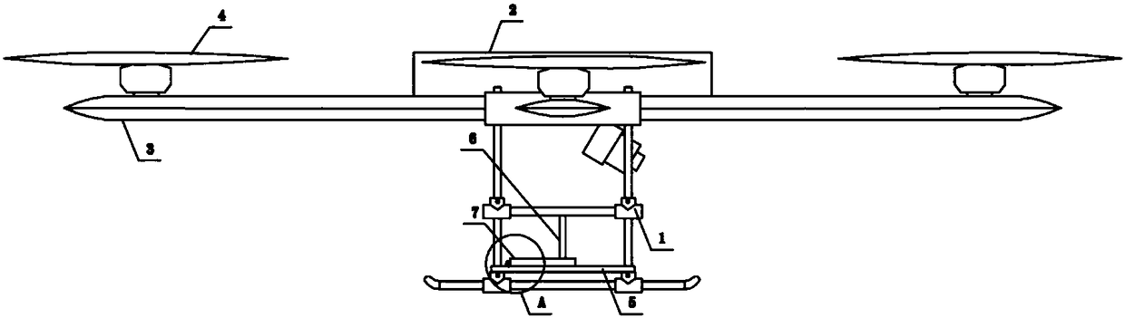
[0029] Such as Figure 1 to Figure 3 As shown, the unmanned aerial vehicle of the present invention adopts the multi-rotor unmanned aerial vehicle in the prior art, and comprises components such as elevating mechanism, control mechanism, power supply and load support 1, and elevating mechanism comprises casing 2 and the lifting mechanism that sets casing 2 around The cross section of the arm 3 and the lifting arm 3 is a shuttle-shaped structure with a thick middle and thin edges. The end of the lifting arm 3 is provided with a propeller 4. The propeller 4 has its own motor. The control mechanism and power supply are arranged inside the casing 2. The control mechanism and the ground The remote control system performs wireless communication and controls the flight state of the drone. The center of gravity adjustment mechanism is arranged at the lower end of the load bracket 1. The center of gravity adjustment mechanism includes a support plate 5, a positioning shaft 6, and a cent...

Embodiment 2

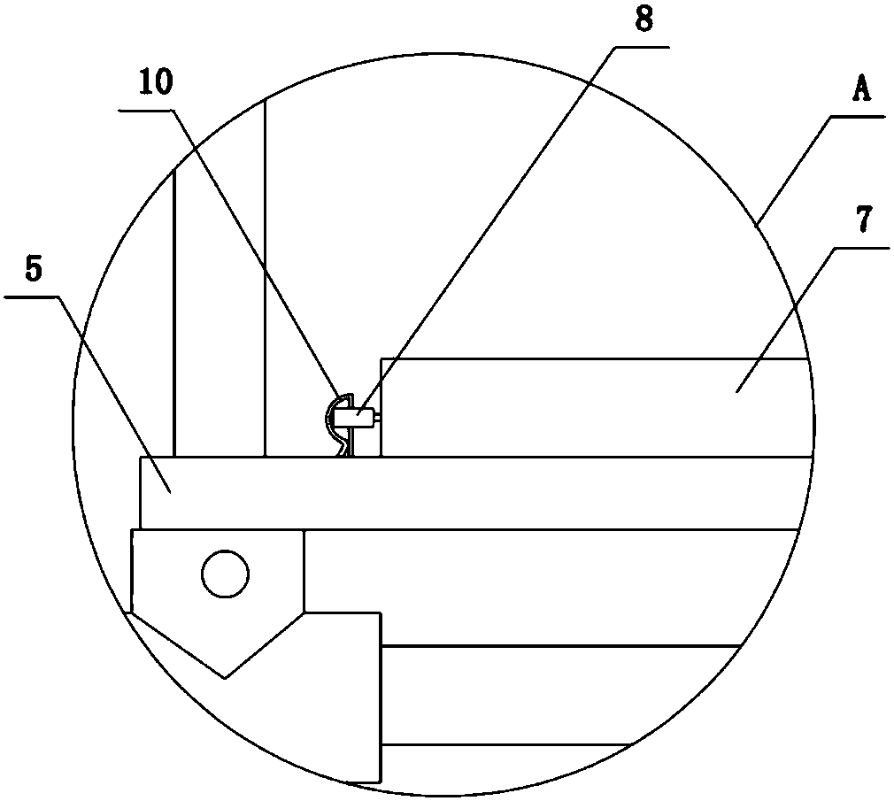
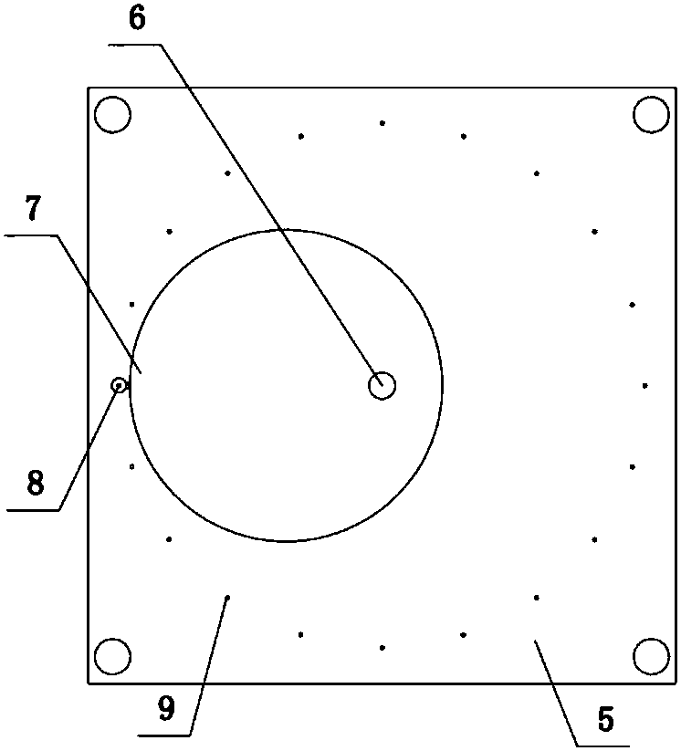
[0031] The structure of this embodiment is basically the same as that of Embodiment 1, the difference is: as Figure 4 and Figure 5 As shown, the bottom of the positioning shaft 6 is evenly fixed to four horizontal rods 11 along the circumferential direction, and the top of the positioning shaft 6 is evenly provided with four grooves 12 along the circumferential direction, and the upper end of the groove 12 is provided with a rotating shaft 13, which is rotated and connected to limit Block 14, a torsion spring is set between the limit block 14 and the groove 12, and the horizontal bar 11 is hinged to the inclined rod 15 at an end far away from the positioning shaft 6, and the upper end of the inclined rod 15 is arranged to engage with the limit block 14. The hook 16 and the tilting rod 15 are sleeved with a counterweight 17 , the bottom of the groove 12 is provided with a first magnet 18 , and the upper end of the tilting rod 15 is provided with a second magnet 19 that is att...

Embodiment 3

[0033] The structure of this embodiment is basically the same as that of Embodiment 1, the difference is: as Figure 5 As shown, there are multiple center-of-gravity adjustment mechanisms. In this embodiment, four are taken as an example, and the four center-of-gravity adjustment mechanisms are evenly arranged.


PUM


Abstract

The invention discloses a multi-functional unmanned aerial vehicle. The vehicle comprises a lifting mechanism, a control mechanism, a power supply and a loading bracket, the lifting mechanism comprises a shell and lifting arms arranged at the periphery of the shell, and propellers are arranged at the end portions of the lifting arms; the propellers are provided with motors, the control mechanism and the power supply are arranged inside the shell, and a gravity center adjusting mechanism is arranged at the lower end of the loading bracket; the gravity center adjusting mechanism comprises a supporting plate, a locating shaft and a gravity center adjusting plate, an eccentric through hole is formed in the gravity center adjusting plate, and the locating shaft is located in the center of the supporting plate; the locating shaft penetrates through the eccentric through hole, suspension loops are arranged on the side wall of the gravity center adjusting plate, a plurality of locating holes corresponding to the suspension loops are formed in the supporting plate, and R-shaped locating pins are arranged on the suspension loops. According to the multi-functional unmanned aerial vehicle, thegravity center adjusting mechanism is arranged at the lower end of the loading bracket, the gravity center adjusting plate is rotatably and eccentrically arranged, so that the gravity center of the whole unmanned aerial vehicle is adjusted, and the gravity center adjusting mechanism is applicable to loading and use of loading equipment with different specifications and shapes.

Description

technical field [0001] The invention belongs to the technical field of unmanned aerial vehicles, and in particular relates to a multifunctional unmanned aerial vehicle. Background technique [0002] Unmanned aircraft, referred to as "unmanned aerial vehicle", or "UAV" in English, is an unmanned aircraft that is controlled by radio remote control equipment and its own program control device, or is completely or intermittently operated autonomously by an on-board computer. [0003] Drones are often better suited for missions that are too "dumb, dirty or dangerous" than manned aircraft. According to the application field, UAVs can be divided into military and civilian use. For civilian use, UAV + industry applications are the real needs of UAVs. Currently, they are used in aerial photography, agriculture, plant protection, miniature selfie, express delivery, disaster relief, Applications in the fields of observing wild animals, monitoring infectious diseases, surveying and map...

Claims


Application Information

Patent Timeline
Patent Type & Authority Applications(China)
IPC IPC(8): B64D47/00B64C39/02
CPCB64C39/02B64D47/00B64U10/10B64U50/19
Inventor 石伟金苗红张超聂高峰姚源
Owner 河南省豫石地质勘查技术有限公司
Why Eureka
Try Eureka