Construction steel-structure lifting and transferring method

A technology of steel and plywood for construction, which is applied in the field of steel structures, and can solve problems such as bending or breaking, increasing procurement expenses for equipment such as rotatable brackets, and affecting construction progress, so as to achieve the effect of firm connection and increased procurement expenses

Inactive Publication Date: 2018-09-21
陈海锋
View PDF1 Cites 5 Cited by
  • Summary
  • Abstract
  • Description
  • Claims
  • Application Information

AI Technical Summary

Problems solved by technology

[0002] At present, the lifting device of the steel structure is realized by a crane. The hook of the crane is connected with a wire rope, and the steel member is placed under the wire rope. When the steel member is lifted, the steel wire will directly grind and bend the steel member. It is easy to cause the thin steel wire on the steel wire rope to be bent or broken during the lifting of the component, and the damage of the steel wire rope is likely to cause a safety hazard for the lifting of the steel component. In addition, the hook of the crane is not flexible. In the prior art, for example, the application The invention patent No. 201420262880.5 includes a main body, and the two ends of the steel structure body are provided with a lifting device, and the lifting device includes a fixed seat fixedly connected with the starter, a rotatable bracket and a steel wire rope, and the rotatable bracket is composed of several connecting rods. Composed of a cardan shaft, the end of the rotatable bracket is provided with a connecting piece connecting the wire rope, the connecting piece is a metal block with a groove on the side, and the metal block is a square structure, a rectangular parallelepiped structure or a spherical structure. Although the invention has a simple structure, there are many deficiencies and defects. In the existing equipment, the design of the connecting rod has defects. When in use, the steel structure body will exert downward bearing capacity on the fixed seat and the rotatable bracket due to its own weight. , the steel structure body is also subjected to the transverse shear force generated by the wind on the steel structure body at high altitude, which makes the connection between the connecting rod and the fixing seat unstable and even causes the connecting rod and the fixing seat to break, which affects the construction progress. The construction quality is reduced, and the purchase cost of maintenance and replacement of rotatable brackets and other equipment is increased, and when the steel structure body is hoisted and transferred on the connecting rod, there is no fixing device, and the steel structure body is easy to slip from both sides of the wire rope, resulting in potential safety hazards, in view of these situations, in order to avoid the above-mentioned technical problems, it is indeed necessary to provide a method for lifting and transferring steel structures for construction to overcome the defects in the prior art

Method used


Image

  • Construction steel-structure lifting and transferring method
  • Construction steel-structure lifting and transferring method
  • Construction steel-structure lifting and transferring method

Examples


Embodiment Construction

[0019] The following will clearly and completely describe the technical solutions in the embodiments of the present invention with reference to the accompanying drawings in the embodiments of the present invention. Obviously, the described embodiments are only some, not all, embodiments of the present invention. Based on the embodiments of the present invention, all other embodiments obtained by persons of ordinary skill in the art without making creative efforts belong to the protection scope of the present invention.

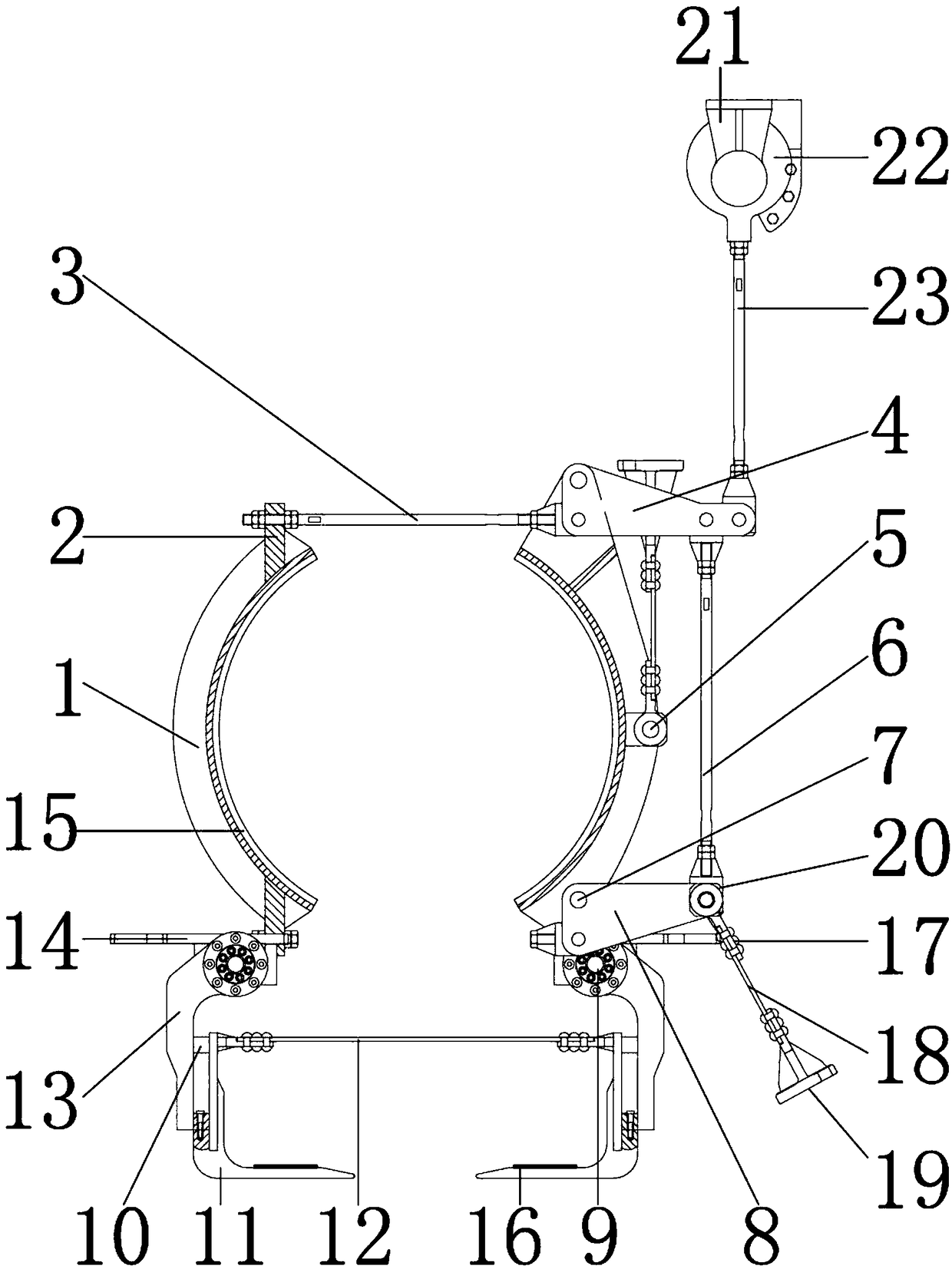
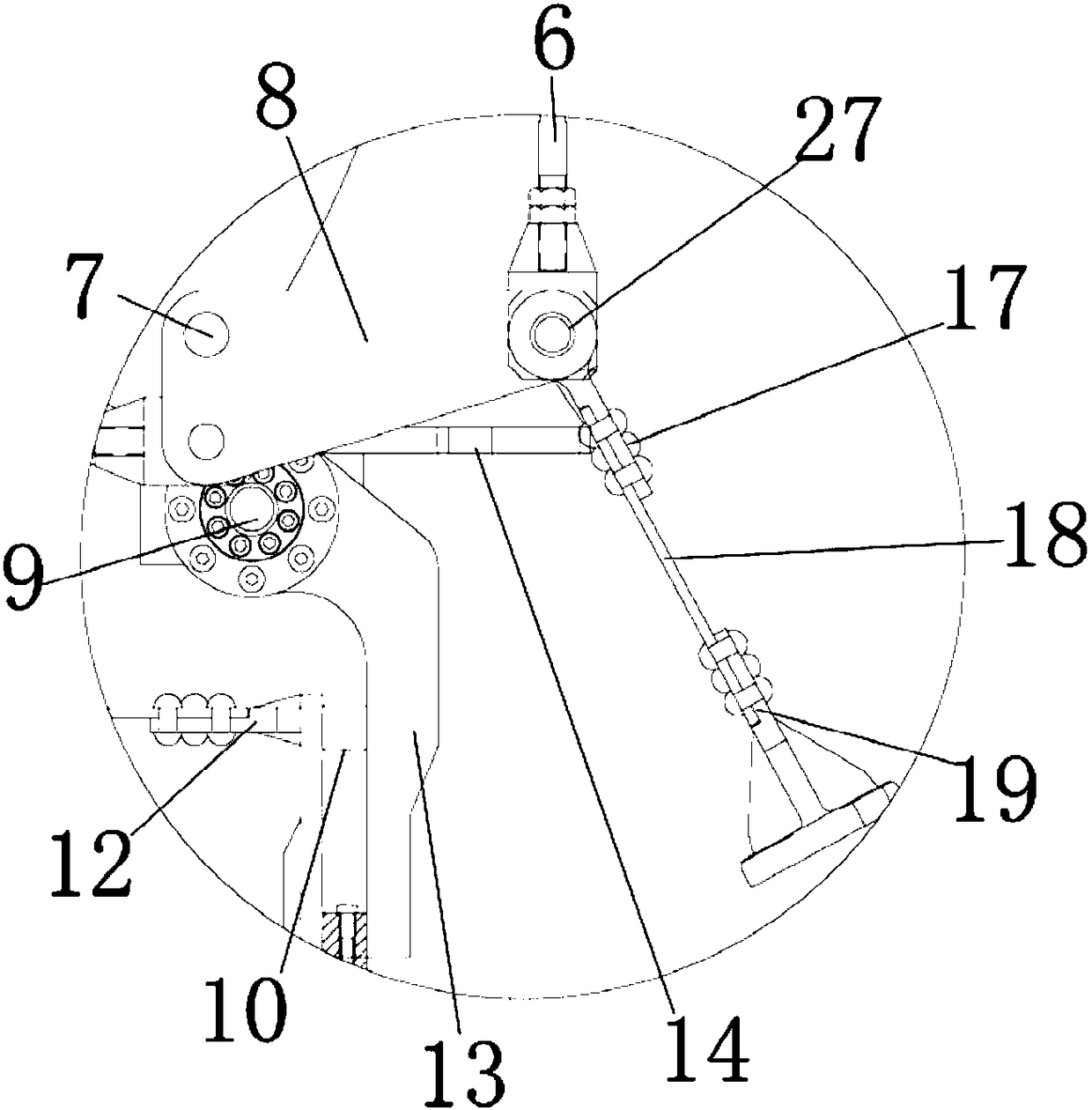
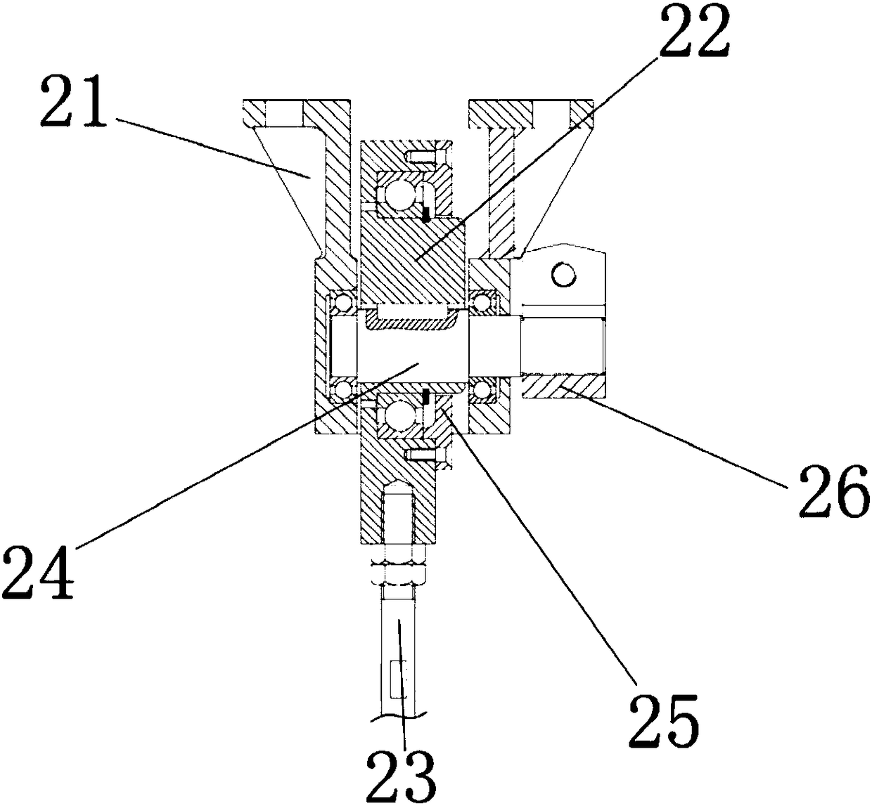
[0020] see Figure 1-3, the present invention provides a technical solution: a method for lifting and transporting a steel structure for construction, including a splint 1 for installing and fixing a side plate 2, and a washer 15 is installed on the inner wall of the splint 1 for increasing frictional force so that the steel structure The connection between the parts and the splint 1 is more firm, the outer wall of the gasket 15 is connected with the inner wal...


PUM


Abstract

The invention discloses a construction steel-structure lifting and transferring method. Side plates are installed at the top ends and the bottom ends of the inner walls of clamping plates, the outer walls of the side plates are connected with the inner walls of the clamping plates, pulling rods are installed on the inner walls of the side plates, the outer walls of the pulling rods are connected with the inner walls of the side plates, supporting plates are installed on the outer walls of the pulling rods, the inner walls of the supporting plates are connected with the outer walls of the clamping plates, and the inner walls of the supporting plates are movably connected with the outer walls of the pulling rods. According to a construction steel-structure lifting and transferring device, through matching between the clamping plates, gaskets and the side plates and under the effect of the pulling rods, the clamping plates clamp steel structure pieces; under the effect of the gaskets, friction force between the clamping plates and the steel structure pieces is increased, connection between the steel structure pieces and the clamping plates is thus firmer, the product quality of the construction steel-structure lifting and transferring device is improved, the procurement cost of enterprise construction is reduced, resource waste of the construction steel-structure lifting and transferring device is avoided, and the construction steel-structure lifting and transferring method and device are suitable for application and popularization.

Description

technical field [0001] The invention relates to the technical field of steel structures, in particular to a lifting and transferring method for steel structures used in construction. Background technique [0002] At present, the lifting device of the steel structure is realized by a crane. The hook of the crane is connected with a wire rope, and the steel member is placed under the wire rope. When the steel member is lifted, the steel wire will directly grind and bend the steel member. It is easy to cause the thin steel wire on the steel wire rope to be bent or broken during the lifting of the component, and the damage of the steel wire rope is likely to cause a safety hazard for the lifting of the steel component. In addition, the hook of the crane is not flexible. In the prior art, for example, the application The invention patent No. 201420262880.5 includes a main body, and the two ends of the steel structure body are provided with a lifting device, and the lifting device...

Claims


Application Information

Patent Timeline
Patent Type & Authority Applications(China)
IPC IPC(8): B66C1/22B66C1/44
CPCB66C1/22B66C1/44
Inventor 陈海锋
Owner 陈海锋
Why Eureka
Try Eureka