Airport demisting system and demisting method

A technology for airports and airport runways, applied in the direction of fog removal, cleaning methods, construction, etc., can solve problems such as the limitation of the function and effect of the blower, the safe operation of the airport, and the lack of fog removal devices, so as to improve the overall traffic order and social reputation. , Improve social and economic benefits, easy to operate

Active Publication Date: 2018-09-21
CIVIL AVIATION UNIV OF CHINA
View PDF6 Cites 0 Cited by
  • Summary
  • Abstract
  • Description
  • Claims
  • Application Information

AI Technical Summary

Problems solved by technology

[0002] At present, there are many patents and products related to demisting devices, but most of them are used for environmental protection and indoor demisting purposes. They have their own designed functions, but there are almost no devices for outdoor large-area space defogging.
Although there is an invention patent that discloses the demisting of the blower, but because the outdoor fog is diffused in a large space, the function and effect of the blower are limited
In addition, although foggy weather can be predicted, it cannot be cleared because there are no conditions and measures
At present, in outdoor spaces such as squares, including airports, if there is fog outside, it will affect the normal work and the safe operation of the airport. The general impact is to reduce or even cancel flights, reduce revenue, and even cause accidents in severe cases. , resulting in loss of life and property

Method used


Image

  • Airport demisting system and demisting method
  • Airport demisting system and demisting method
  • Airport demisting system and demisting method

Examples


Embodiment Construction

[0024] The airport defogging system and defogging method provided by the present invention will be described in detail below in conjunction with the accompanying drawings and specific embodiments.

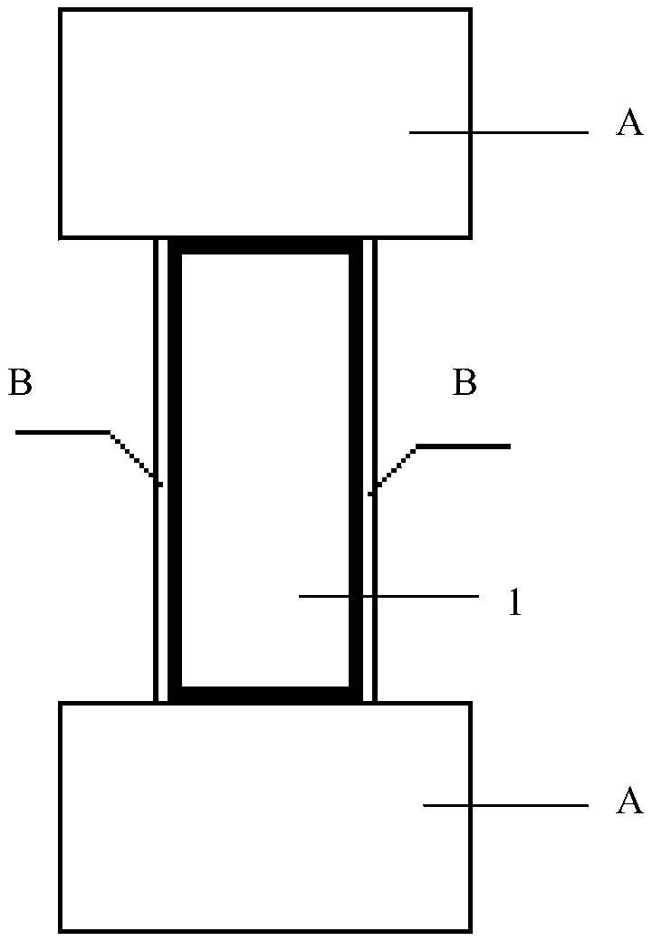
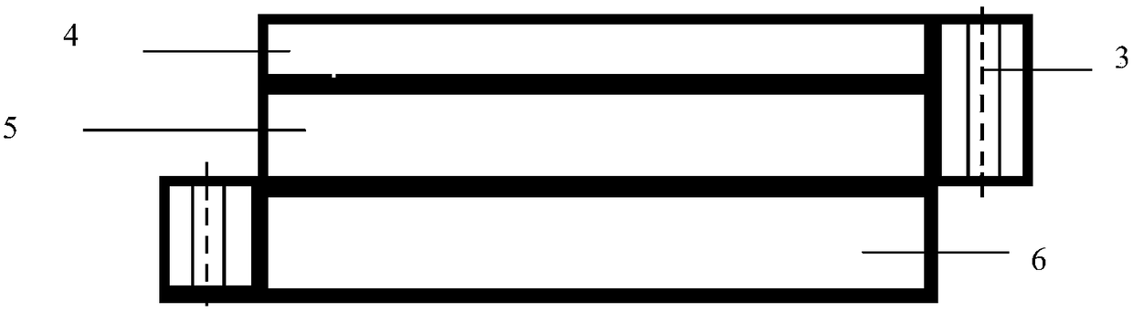
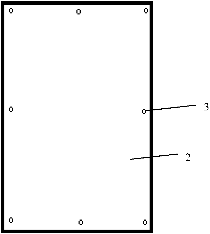
[0025] Such as figure 1 — Figure 4 As shown, the airport defogging system provided by the present invention includes a plurality of outdoor defogging electric heating blanket bodies 2, steel brazing or strapping; wherein a plurality of outdoor defogging electric heating blanket bodies 2 are laid on airport runways, taxiways or connecting roads 1 On the ground in the end area A outside both ends and the side area B outside both sides, the outdoor demisting electric heating blanket body 2 has a rectangular structure, and a plurality of connection holes 3 are formed on the edge; the end area A is Rectangular, the length direction is parallel to the length direction of the airport runway, taxiway or connecting road 1, its length and width can be selected according to the fog concentr...


PUM


Abstract

The invention discloses an airport demisting system and a demisting method. The system comprises a plurality of outdoor demisting electric heating blanket bodies, a steel chisel, a strapping tape andan electric heating power source system. The airport demisting system has the advantages that the local visibility near the outdoor large-area terrain can be improved under the mist condition, and larger benefits are achieved when the system is applied to busy or large airports. During use, only transporting, loading and unloading are needed, demounting and mounting are convenient, the system canbe stored to be used many times, special maintenance is not needed, and operation is easy and convenient. The power is adjustable, demisting is carried out by changing the local air temperature condition of the low altitude, and then the visibility of the local area of the low altitude is improved. Environmental pollution is avoided, and the system can be used for a short time according to the mist condition and needs. Safe flight can be guaranteed by improving the visibility, social benefits, economic benefits and the technology and management level can be improved, service quality can be improved, and the comprehensive traffic order and the social reputation of civil aviation are improved. Then the hourly rate of the airports, runways and airplanes are increased, the effects of increasing revenue and reducing expenditure are achieved, the flight delay rate caused by the mist can be reduced, and the annual flight on-time performance statistical level is greatly improved.

Description

technical field [0001] The invention belongs to the technical field of airport auxiliary equipment and methods, and in particular relates to an airport defogging system and a defogging method. Background technique [0002] At present, there are many patents and products related to defogging devices, but most of them are used for environmental protection and indoor defogging purposes. They have their own designed functions, but there are almost no devices for outdoor large-area space defogging. . Although there is an invention patent disclosure related to blower demisting, because the outdoor fog is diffused in a large space, the function and effect of the blower are limited. In addition, although foggy weather can be predicted, the fog cannot be cleared because there are no conditions and measures. At present, in outdoor spaces such as squares, including airports, if there is fog outside, it will affect the normal work and the safe operation of the airport. The general imp...

Claims


Application Information

Patent Timeline
Patent Type & Authority Applications(China)
IPC IPC(8): E01H13/00
CPCE01H13/00
Inventor 赵文智王艳红张晓全魏然刘嫣张莉梅李辉王媛卓马红亮曾刚石志强杨磊
Owner CIVIL AVIATION UNIV OF CHINA
Why Eureka
Try Eureka